
Device for determining position of at least one object

A technology for equipment and objects, applied in devices with multiple detectors, measuring devices, using re-radiation, etc., which can solve problems such as eye safety hazards, inability to increase frame rate, crosstalk, etc.

Pending Publication Date: 2019-10-29
ROBERT BOSCH GMBH
View PDF7 Cites 0 Cited by
  • Summary
  • Abstract
  • Description
  • Claims
  • Application Information

AI Technical Summary

Problems solved by technology

On the one hand, temporally and spatially concentrated lighting that is a hazard to the eye safety of users or other non-participating persons
On the other hand, due to the spatial concentration of the illumination power, saturation effects caused by light-colored objects in the near field, the possibility of crosstalk with other flash systems, the high peak power required and the lack of adaptive grounding in operation are also obtained. Possibility of matching field of view
Finally, the frame rate cannot be increased without increasing the lighting power relevant for eye safety, since the individual emitters cannot be switched off for compensation

Method used


Image

  • Device for determining position of at least one object
  • Device for determining position of at least one object
  • Device for determining position of at least one object

Examples


Embodiment Construction

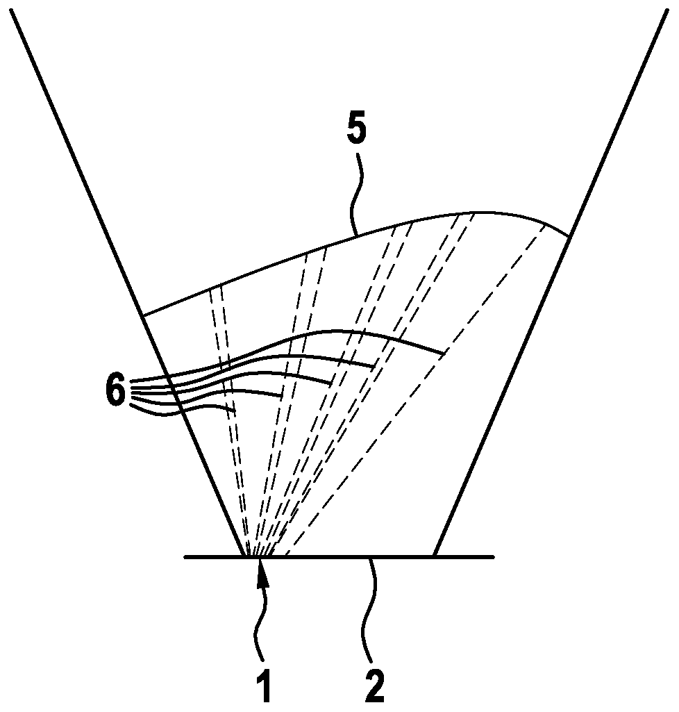
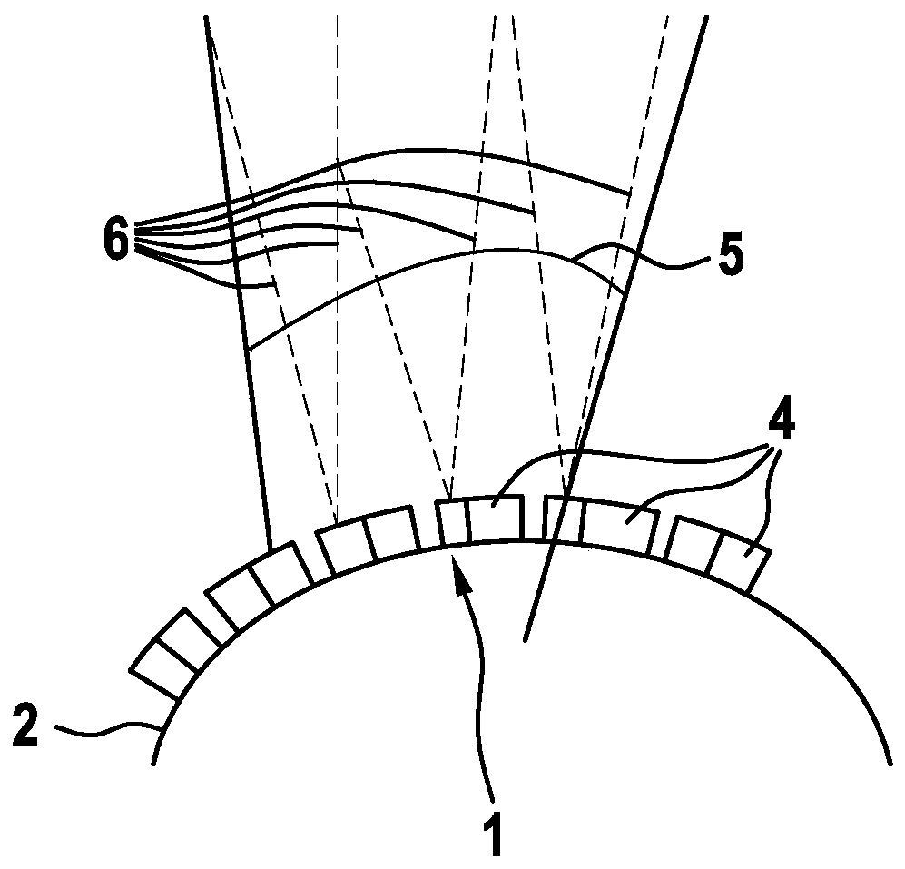
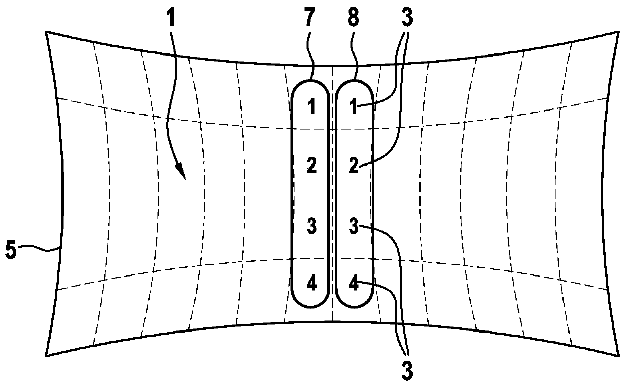
[0031] exist figure 1 A detail of a device for determining the position of at least one object is schematically shown in . In this case, the device has an emitter array 1 which is arranged on a carrier element 2 . Here, the emitter array 1 comprises a plurality of emitters 3 which are arranged on a circuit board 4 (see figure 2 ). Furthermore, the device has a schematically indicated field of view 5 . Each of these emitters 3 is set up to cover an illuminated area 6 .

[0032] In this case, the individual transmitters 3 can be actuated individually. as in figure 1 As intuitively illustrated in , the individual illumination areas 6 of the emitters 3 are disjoint and completely cover the field of view 5 of the device. In this case, the illuminated areas 6 illuminated by the emitters 3 directly adjoin one another, without overlapping and without gaps.

[0033] In the illustrated embodiment of the device, the carrier element 2 is configured as a plane (that is to say a car...


PUM


Abstract

A device for determining a position of at least one object is described, the device including an emitter array (1), which is configured to cover a field of view (5) of the device, and which includes at least two emitters, which are situated on a support element (2), each emitter (3) being configured to cover an illumination area (6). The device provides that the emitters (3) are individually controllable, the illumination area (6) of the emitters being disjunctive and covering the field of view (5) of the device.

Description

technical field [0001] The invention relates to a device for determining the position of at least one object, wherein the device has an array of emitters arranged to cover the field of view of the device, and the array of emitters has at least Two emitters are arranged on the carrier element, wherein each emitter is designed to cover a lighting area. Background technique [0002] Such devices are also known as LiDAR (the word is derived from light and radar). Such LiDAR systems are currently typically implemented as rotating scanners, microscanners, or flash systems. Here, so-called solid-state LiDAR systems have certain advantages. These solid-state LiDAR systems have no mechanically moving parts. As a result, on the one hand, mechanical devices and deflection mechanisms can be saved, and on the other hand, defects can be prevented. [0003] The emitter array of the device is set up to cover the field of view (English: field of view, FOV) of the device. The emitter arr...

Claims


Application Information

Patent Timeline
Patent Type & Authority Applications(China)
IPC IPC(8): G01S7/481G01S17/06
CPCG01S7/481G01S17/06G01S17/42G01S7/4815G01S7/484G01J1/4228G01J1/08G01J1/4209
Inventor M·卡米尔N·霍伊斯纳
Owner ROBERT BOSCH GMBH
Learn More