Force sensor type harmonic reducer
A harmonic reducer and sensor-type technology, which is applied in the direction of mechanical equipment, transmission devices, transmission device parts, etc., can solve the problems of increasing the complexity of the robot structure, low sensitivity, and reducing the rigidity of the robot transmission.
- Summary
- Abstract
- Description
- Claims
- Application Information
AI Technical Summary
Problems solved by technology
Method used
Image
Examples
Embodiment 1
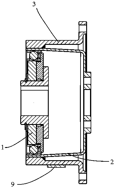
[0034] Embodiment 1: as figure 1 As shown, the double-flexible pulley force-sensing type harmonic reducer includes a strong-flexible pulley, a weak-flexible pulley, a wave generator and a strain gauge. Both the strong-flexible pulley and the weak-flexible pulley are equipped with mounting flanges, so The soft spline described above is processed by using the processing technology of the existing flexible spline of the harmonic reducer and the steel material 40CrMoTi commonly used for the flexible spline. The strong and soft wheels and the weak and soft wheels are respectively processed with teeth that can mesh with each other. The weak and soft wheels are external teeth and the strong and soft wheels are internal teeth. Trapezoidal teeth are selected. The weak and soft wheels are selected from most existing harmonic soft wheels. The reducer has the same thin-walled cup shape, and the strong and soft wheel adopts the shape of the flanging soft wheel and the wall thickness is 3 t...
Embodiment 2
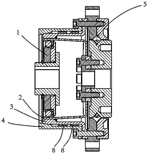
[0035] Embodiment 2: as figure 2As shown, the double flex spline force sensor type harmonic reducer with limitable deformation includes strong flex spline, weak flex spline, wave generator, strong flex spline deformation limiting parts, reducer main bearing and 4 pieces of strain The main bearing of the reducer is a cross roller bearing. The strong and soft wheels and the weak and soft wheels are equipped with mounting flanges. The strong and soft wheels and the weak and soft wheels are connected to the reducer by bolts respectively The outer ring and the inner ring of the main bearing are fixed. The soft wheel is processed by using the processing technology of the soft wheel of the existing harmonic reducer and the steel materials commonly used for the soft wheel. The strong and flexible wheel is processed by using the existing harmonic reducer The processing technology of the flex wheel is made of high-hardness bronze. The strong and soft wheels and the weak and soft wheels...
Embodiment 3
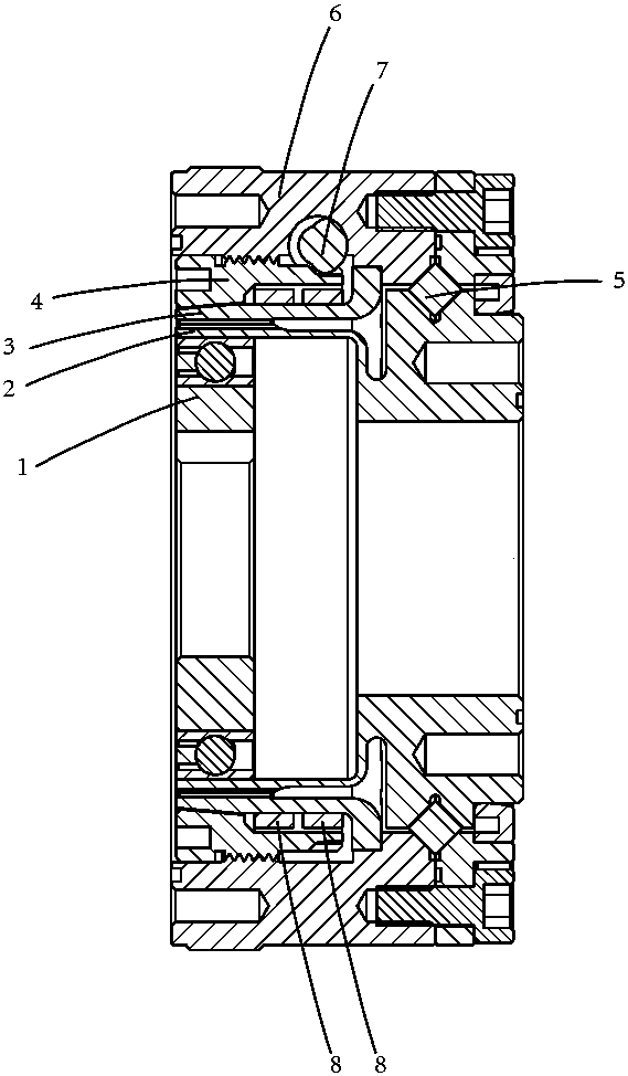
[0036] Embodiment 3: as image 3 As shown, the precision compensation force sensing type harmonic reducer includes the outer flexible spline, the inner flexible spline, the wave generator, the deformation limit part of the outer flexible spline, the precision compensation adjustment worm, the shell components, the main bearing of the reducer and 4 One end of the tubular wall of the outer flexspline is connected and fixed to the shell component, and the other end of the tubular wall of the outer flexspline is provided with 202 internal teeth, and the inner flexspline and the outer flexspline are axially fixed and radially Fixed, the inner flexspline is equipped with 200 external teeth that can mesh with the inner gear of the outer flexspline. Both the inner and outer flexsplines use trapezoidal teeth. The elliptical elastic deformation occurs, the position of the long axis of the ellipse meshes with the internal teeth of the outer flexspline, and the contact part of the outer f...
PUM
 Abstract
Description
Claims
Application Information
 - R&D
- Intellectual Property
- Life Sciences
- Materials
- Tech Scout
- Unparalleled Data Quality
- Higher Quality Content
- 60% Fewer Hallucinations
Browse by: Latest US Patents, China's latest patents, Technical Efficacy Thesaurus, Application Domain, Technology Topic, Popular Technical Reports.
© 2025 PatSnap. All rights reserved.Legal|Privacy policy|Modern Slavery Act Transparency Statement|Sitemap|About US| Contact US: help@patsnap.com


