
Polishing apparatus

A technology of grinding device and grinding pad, applied in grinding device, grinding machine tool, grinding workpiece support, etc., can solve problems such as uneconomical and spread of slurry, and achieve the effect of restraining the consumption of slurry and restraining consumption.

Active Publication Date: 2019-10-29
DISCO CORP
View PDF5 Cites 0 Cited by
  • Summary
  • Abstract
  • Description
  • Claims
  • Application Information

AI Technical Summary

Problems solved by technology

[0004] However, in the polishing device described in Patent Document 1, when the amount of slurry provided is relatively small relative to the rotational speed of the polishing pad, centrifugal force alone cannot make the The slurry spreads to the outer peripheral side, and as a result, the slurry is not spread over the entire polishing surface of the polishing pad for polishing
Therefore, it is uneconomical to make the supplied slurry rotate at a higher speed relative to the grinding pad so that the slurry is spread over the entire grinding surface by centrifugal force while grinding.

Method used


Image

  • Polishing apparatus
  • Polishing apparatus
  • Polishing apparatus

Examples


Embodiment Construction

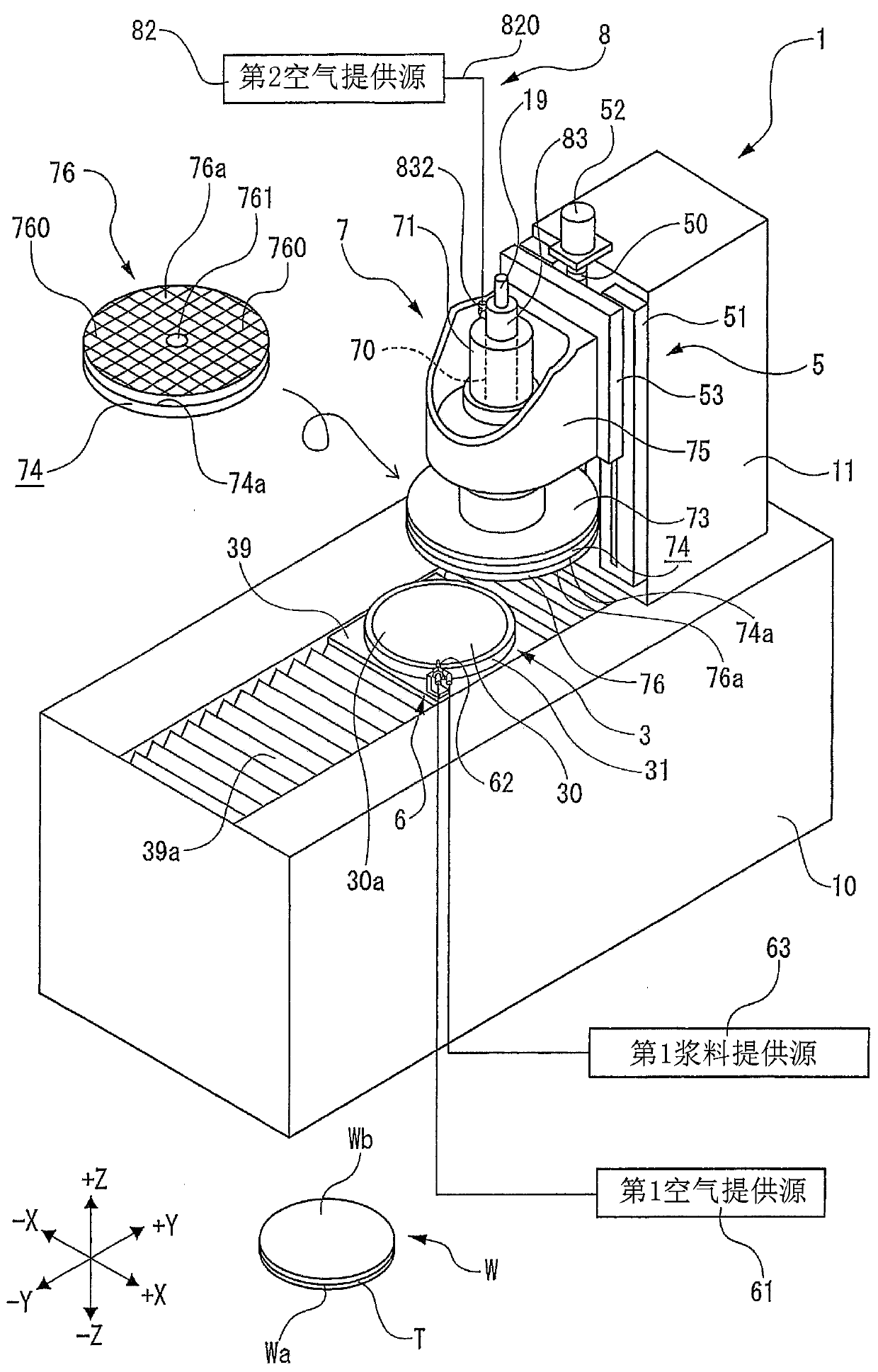
[0018] figure 1 The illustrated polishing device 1 is a device for polishing a wafer W held on a holding table 3 by using a polishing pad 76 attached to a spindle 70 having an axis in the vertical direction (Z-axis direction). : a device base 10 extending in the Y-axis direction; and a column 11 erected on the rear side of the device base 10 in the Y-axis direction.

[0019] figure 1 The wafer W shown is, for example, a circular plate-shaped semiconductor wafer made of silicon or the like. figure 1 Among them, the upper surface Wb facing upward becomes the surface to be polished. exist figure 1 Among them, for example, a plurality of devices are formed on the lower surface Wa of the wafer W facing downward, and the plurality of devices are protected by sticking a protective tape T thereon. In addition, the wafer W is not limited to the example shown in this embodiment.

[0020] The diameter of the wafer W is, for example, 300 mm or 200 mm.

[0021] The holding table 3 ha...


PUM


Abstract

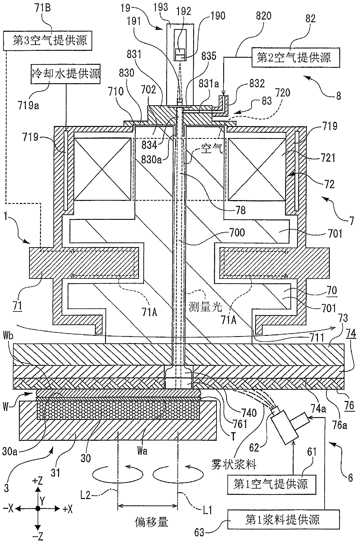
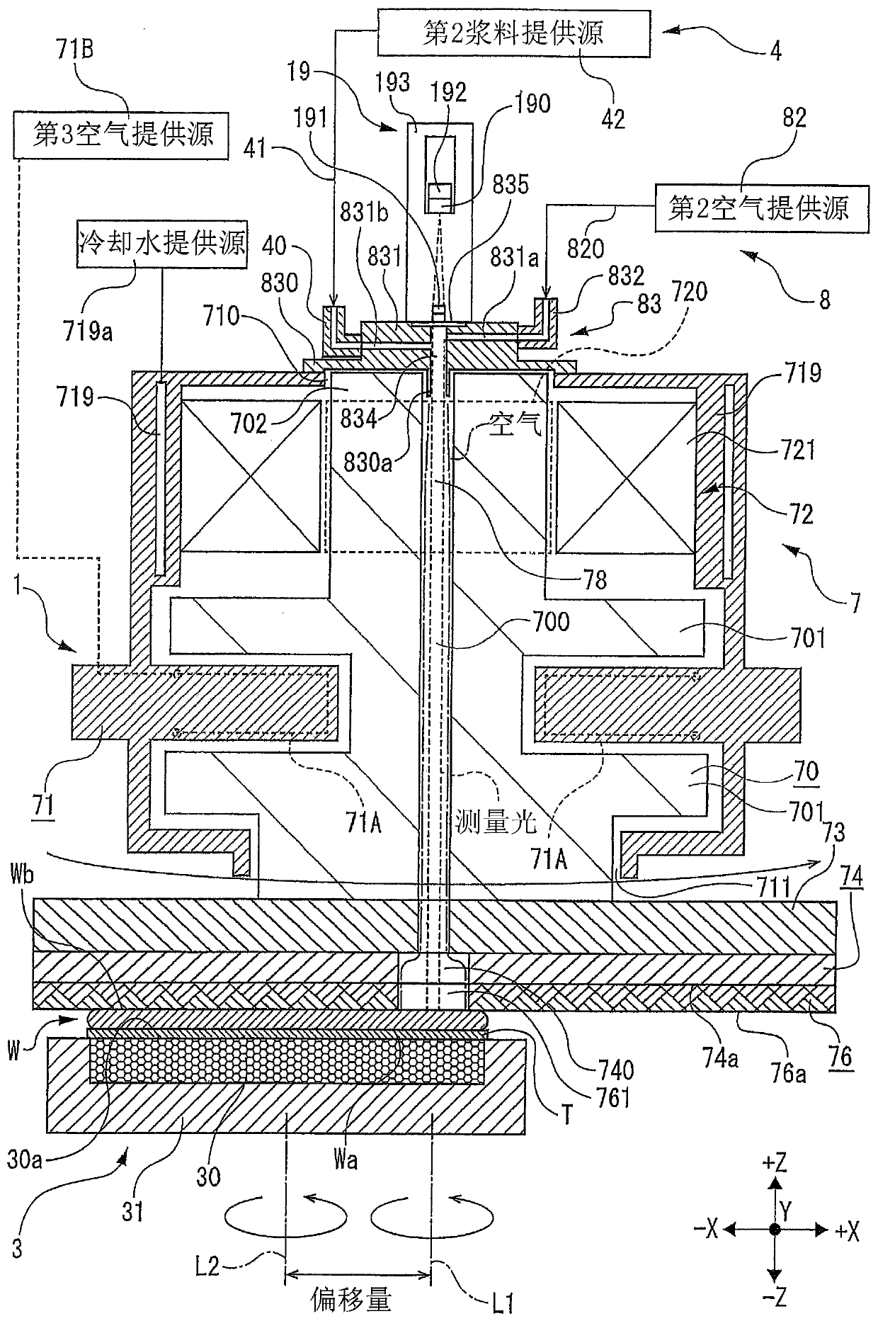
Provided are a polishing device that suppresses the amount of slurry supplied while spreading the slurry over the entire polishing surface of the polishing pad, thereby achieving economical polishingprocessing that suppresses slurry consumption. The polishing apparatus includes a wafer holding table, a polishing unit in which a polishing pad having an opening at the center of a polishing surfacethat polishes the wafer is mounted to a spindle and is rotated, a slurry supply unit that supplies slurry to the polishing surface of the polishing pad, and an air supply unit that shuts an upper endof a penetrating path penetrating through the axial center of rotation of the polishing pad and the spindle and supplies air into the penetrating path. The polishing device sprays air provided by an air supply unit on the upper surface of the wafer sealed with the polishing pad's opening by contacting the upper surface of the wafer held by the holding table with the polishing surface of the polishing pad, and spreads the slurry over the entire polishing surface by the flow of radial air from the opening toward the outer periphery in the direction of the polishing surface so as to polish the wafer.

Description

technical field [0001] The present invention relates to a grinding device for grinding wafers. Background technique [0002] A lapping device (for example, refer to Patent Document 1) for lapping a wafer has: a chuck table that uses a holding surface to attract and hold the wafer and can rotate around the center of the holding surface; a rotation unit that makes the chuck The table rotates around the center of the holding surface; the polishing unit has a main shaft that rotates around the center of the mounting seat on which the polishing pad is mounted; and the slurry supply unit is formed through the shaft center of the main shaft The slurry is supplied from the opening formed in the center of the polishing pad through the through passage. The polishing device supplies the slurry from the opening in the center of the polishing pad, and uses the centrifugal force of the rotating polishing pad to spread the slurry over the entire polishing surface to treat the wafer. Grind...

Claims


Application Information

Patent Timeline
Patent Type & Authority Applications(China)
IPC IPC(8): B24B37/00B24B37/34
CPCB24B37/00B24B37/34B24B37/005B24B37/04B24B37/30B24B41/061B24B49/04H01L22/12B24B57/02H01L21/30625H01L21/304
Inventor 井上雄贵铃木孝雅
Owner DISCO CORP
Learn More