Puncture needle head with edge sides and visual puncture needle
A puncture needle and edge technology, applied in the field of puncture device, can solve the problems of high potential risk of visceral tissue, complex product structure, large tissue damage, etc., and achieve the effect of shortening operation time, simple structure and reducing injury
- Summary
- Abstract
- Description
- Claims
- Application Information
AI Technical Summary
Problems solved by technology
Method used
Image
Examples
Embodiment 1
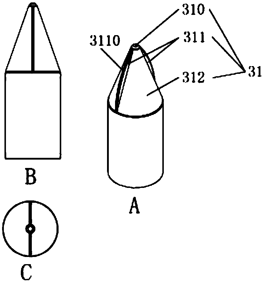
[0037] Such as figure 1 Shown is a schematic view of the structure of the puncture needle with a blade edge in Embodiment 1. The edged puncture needle 31 includes a positioning head 310 , two double edged edges 311 and a tapered guide body 312 . The positioning head 310 is located at the front end of the tapered guide body 312 , and the two double-edged edges 311 are symmetrically arranged on the outer surface of the tapered guide body 312 . In this embodiment, the four cutting edges of the two double-edged edges 311 are all round cutting edges 3110 .
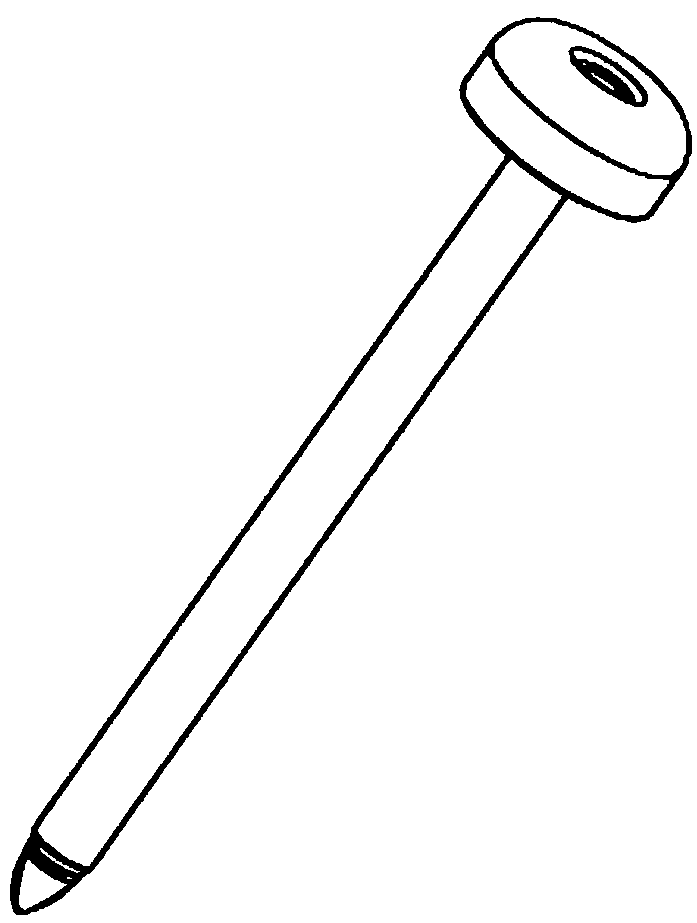
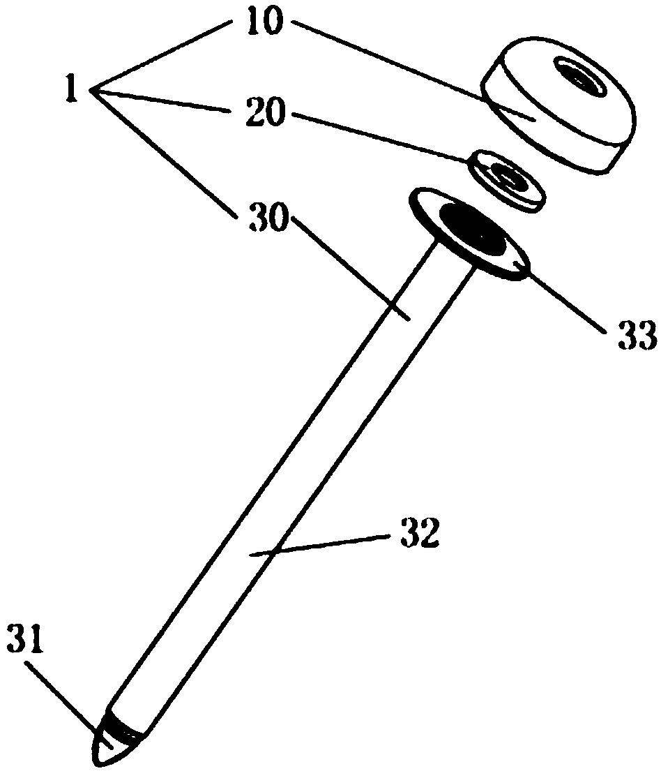
[0038] Such as figure 2 with 3 Shown is a schematic diagram of the visible puncture needle of the present invention. The puncture needle 1 includes a needle cover 10 , a fixing ring 20 and a needle tube 30 .
[0039] Such as Figure 4 As shown, the needle cover 10 has a connecting ring 100, an outer ring 102 and a needle cover hole 103; the connecting ring 100 is arranged on the inner surface of the outer ring 102 and ha...
Embodiment 2
[0046] Such as Figure 8 Shown is a schematic view of the structure of the puncture needle with the edge of the second embodiment. The edged puncture needle 31 includes a positioning head 310 , two double edged edges 311 , a tapered guide body 312 and a protective body 313 . The positioning head 310 is located at the front end of the tapered guide body 312 , two double-edged edges 311 are symmetrically arranged on the outer surface of the tapered guide body 312 , and the protection body 313 is located at the rear end of the tapered guide body 312 . In this embodiment, the four cutting edges of the two double-edged edges 311 are all round cutting edges 3110 . Setting the protective body 313 can further reduce the damage to the tissue caused by the double-edged edge 311, and can also increase the sealing between the abdominal wall tissue and the puncture tube.
Embodiment 3
[0048] Such as Figure 9Shown is a schematic view of the structure of the puncture needle with the edge of the embodiment 3. The edged puncture needle 31 includes a positioning head 310 , two double edged edges 311 , a tapered guide body 312 , a protective body 313 and a positioning guide body 314 . The positioning guide body 314 is located at the front end of the tapered guide body 312, the positioning head 310 is located at the front end of the positioning guide body 314, two double-edged edges 311 are symmetrically arranged on the outer surface of the tapered guide body 312, and the protective body 313 is positioned at the front end of the tapered guide body 312. The rear end of the body 312. In this embodiment, the four cutting edges of the two double-edged edges 311 are all round cutting edges 3110 . Setting the protective body 313 can further reduce the damage to the tissue caused by the double-edged edge 311, and can also increase the sealing between the abdominal wal...
PUM
 Abstract
Description
Claims
Application Information
 - R&D
- Intellectual Property
- Life Sciences
- Materials
- Tech Scout
- Unparalleled Data Quality
- Higher Quality Content
- 60% Fewer Hallucinations
Browse by: Latest US Patents, China's latest patents, Technical Efficacy Thesaurus, Application Domain, Technology Topic, Popular Technical Reports.
© 2025 PatSnap. All rights reserved.Legal|Privacy policy|Modern Slavery Act Transparency Statement|Sitemap|About US| Contact US: help@patsnap.com


