Grid-connected system and method of thermoacoustic generating set

A technology of generator set and thermoacoustic engine, applied in the direction of single-grid parallel feeding arrangement, etc., can solve problems such as power loss

Active Publication Date: 2020-12-11
TECHNICAL INST OF PHYSICS & CHEMISTRY - CHINESE ACAD OF SCI
View PDF6 Cites 0 Cited by
  • Summary
  • Abstract
  • Description
  • Claims
  • Application Information

AI Technical Summary

Problems solved by technology

[0005] Aiming at the problems existing in the prior art, the embodiment of the present invention provides a grid-connected system and method of a thermoacoustic generating set, which is used to solve the defect in the prior art that the electric energy is lost through inversion, and realizes that the thermoacoustic generating set does not need inverter Can be connected to the grid

Method used


Image

  • Grid-connected system and method of thermoacoustic generating set
  • Grid-connected system and method of thermoacoustic generating set
  • Grid-connected system and method of thermoacoustic generating set

Examples


Embodiment 1

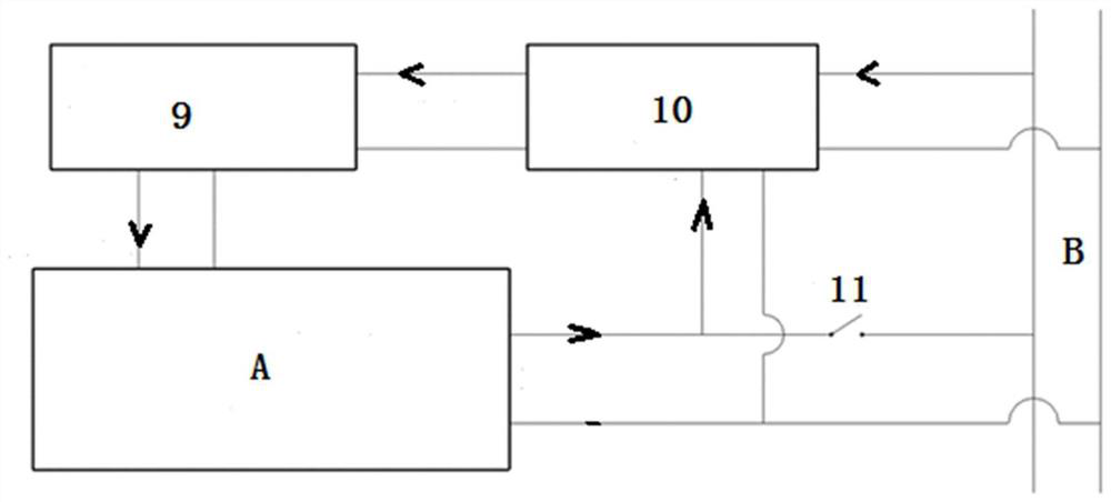
[0019] This embodiment provides a grid-connected system for a thermoacoustic generator set, the schematic diagram of which is as follows: figure 1 As shown, the grid-connected system includes: a phase-locking device 10, a signal amplifier 9, a thermoacoustic generator set A and an access switch 11. An input end of the phase-locking device 10 is connected to the power grid B, and an output end of the phase-locking device 10 is connected to the power grid B. The input end of the signal amplifier 9 is connected, the output end of the signal amplifier 9 is connected to the input end of the thermoacoustic generator set A, the output end of the thermoacoustic generator set A is connected to the grid B, and the output end of the thermoacoustic generator set A is connected to the grid B There is an access switch 11 in between, and the other input end of the phase locking device 10 is connected between the output end of the thermoacoustic generator set A and the access switch 11, so tha...

Embodiment 2

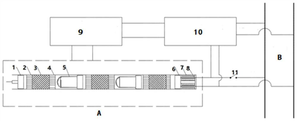
[0023] Based on Embodiment 1, this embodiment provides a specific grid-connected system for thermoacoustic generator sets, the specific structure of which is as follows figure 2 As shown, the thermoacoustic generator set A includes multiple sets of thermoacoustic engines serially connected between the compressor piston 1 and the generator piston 6, and each set of thermoacoustic engines is coupled through the ejector 5, and the thermoacoustic engine includes The main water cooler 2 , the regenerator 3 and the heater 4 are connected secondary, the main water cooler 2 is connected with the compressor piston 1 , and the thermoacoustic generator set A also includes a permanent magnet 7 and a coil 8 connected with the generator piston 6 .

[0024] The compressor piston 1 moves repeatedly under the driving of the external voltage and compresses the gas inside the unit, so that it generates oscillating sound waves. The mechanical energy of the engine is multiplied and input into the...

Embodiment 3

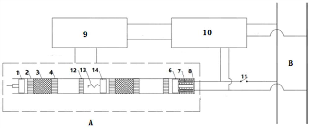
[0026] Based on Embodiment 1, this embodiment provides another grid-connected system for thermoacoustic generator sets, the schematic diagram of which is as follows image 3 As shown, the thermoacoustic generator set A includes multiple sets of thermoacoustic engines serially connected between the compressor piston 1 and the generator piston 6, and the resonance between each set of thermoacoustic engines is formed by the mass piston 14 and the resonant spring 13 The sub-assemblies are coupled, the thermoacoustic engine includes a main water cooler 2, a regenerator 3, a heater 4 and a secondary water cooler 12 connected in sequence, the main water cooler 2 is connected to the compressor piston 1, and the secondary water cooler 12 is connected to the heater. Between 4 and the resonance spring 13 , the thermoacoustic generator set A further includes a permanent magnet 7 and a coil 8 connected with the generator piston 6 .

[0027] Among them, the resonant sub-assembly can make th...


PUM


Abstract

The embodiment of the invention provides a grid-connected system and method of a thermo-acoustic generator set. The grid-connected system comprises a phase locking device, a signal amplifier, the thermo-acoustic generator set and an access switch; one input end of the phase locking device is connected with a power grid; the output end of the phase locking device is connected with the input end ofthe signal amplifier; the output end of the signal amplifier is connected with the input end of the thermo-acoustic generator set; the output end of the thermo-acoustic generator set is connected intoa power grid; the access switch is arranged between the output end of the thermo-acoustic generator set and the power grid; the other input end of the phase locking device is connected between the output end of the thermo-acoustic generator set and the access switch. The output of the thermo-acoustic generator set is controlled through the phase locking device and the signal amplifier, so that the output is matched with the amplitude, phase and frequency of a power grid voltage and the output power of the thermo-acoustic generator set is directly connected into a public power grid, thereby avoiding the inversion process, reducing the loss of electric energy, solving the problem of difficulty in grid connection, and promoting the development of the thermo-acoustic power generation technology.

Description

technical field [0001] The embodiments of the present invention relate to the technical field of thermoacoustic power generation, and in particular, to a grid-connected system and method for a thermoacoustic generator set. Background technique [0002] A thermoacoustic engine refers to a device that generates mechanical power from heat through the thermoacoustic effect, which is a physical phenomenon in which heat causes acoustic self-excited oscillations in an elastic medium (usually high-pressure inert gas). The thermoacoustic engine converts low-grade thermal energy into mechanical energy in the form of acoustic pressure waves, and then the linear oscillating motor (as an acoustic-electric conversion device) generates electricity and converts it into electrical energy, forming a thermoacoustic generator. Multiple sets of thermoacoustic engines are connected in series between the compressor generators to form a thermoacoustic generator set. The thermoacoustic generator se...

Claims


Application Information

Patent Timeline
Patent Type & Authority Patents(China)
IPC IPC(8): H02J3/44H02J3/42
CPCH02J3/42H02J3/44
Inventor 胡剑英孙岩雷罗二仓张丽敏罗开琦胡江风
Owner TECHNICAL INST OF PHYSICS & CHEMISTRY - CHINESE ACAD OF SCI
Why Eureka
Try Eureka