Air filtering dust prevention power distribution cabinet capable of achieving automatic cleaning
A technology for automatic cleaning and power distribution cabinets, which is applied to substation/power distribution device casings, electrical components, substation/switch layout details, etc., can solve the problems of air permeability decline, regular manual cleaning, inconvenience, etc., and achieve improved dust removal effect of effect
- Summary
- Abstract
- Description
- Claims
- Application Information
AI Technical Summary
Problems solved by technology
Method used
Image
Examples
Embodiment 1
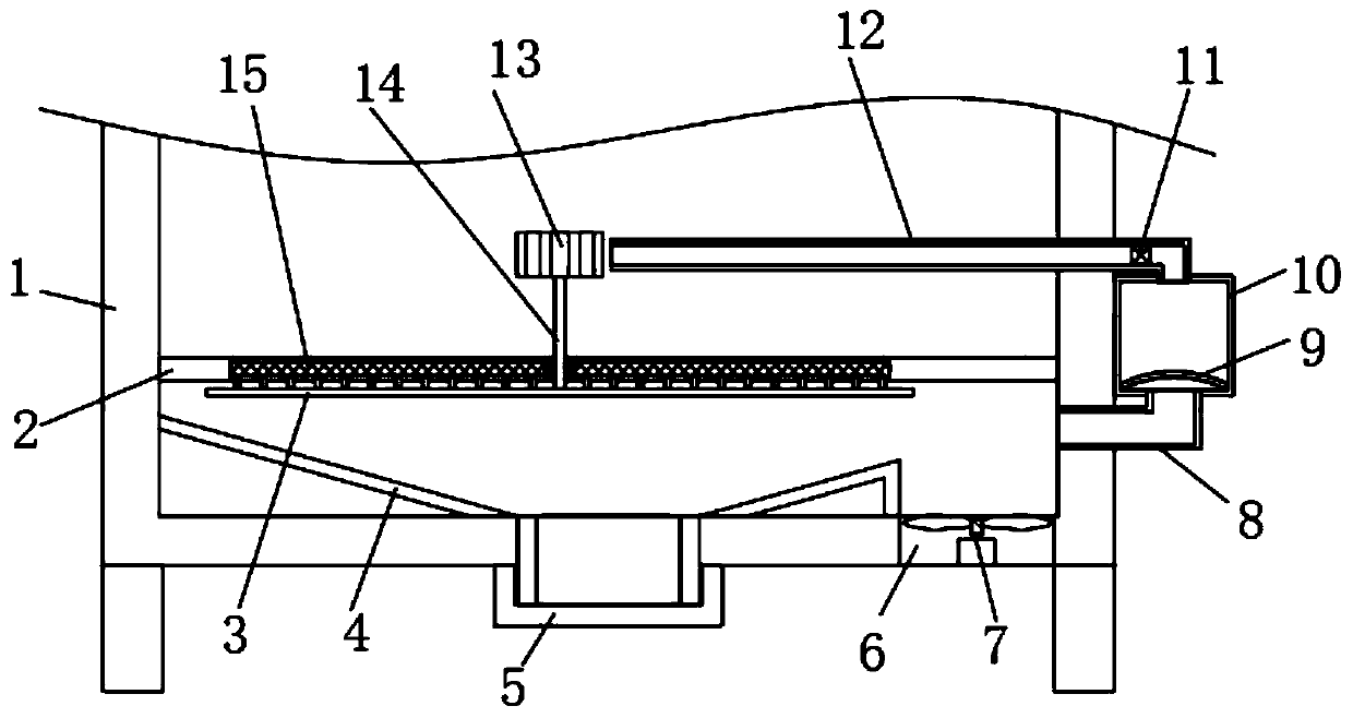
[0019] refer to figure 1 , a self-cleaning air-filtering and dust-proof power distribution cabinet, comprising a cabinet body 1, the interior of the cabinet body 1 is fixedly connected with a fixed plate 2, and the fixed plate 2 divides the interior of the cabinet body 1 into equipment chambers arranged up and down and The air filter chamber is equipped with an ash hopper 4 connected to the outside, the cleaned dust can fall into the ash hopper 4 for concentration, the lower end of the ash hopper 4 is connected with a cover 5, and the cover 5 is threaded with the ash hopper 4 connection, it is convenient to remove the cover 5 to clean up the ash in the ash hopper 4, the lower end of the cabinet body 1 is provided with an air inlet 6, the air inlet 6 is provided with an air inlet fan 7, and the fixed plate 2 is embedded with two A filter chip 15, the fixed plate 2 is vertically penetrated with a rotating shaft 14 that is connected to it in rotation, the lower end of the rotatin...
Embodiment 2
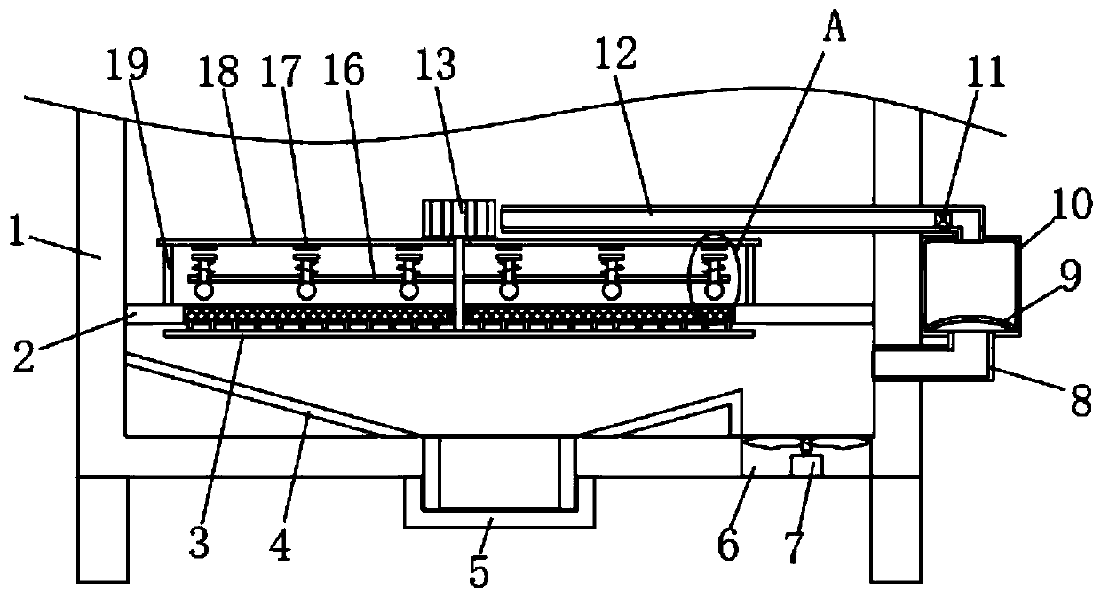
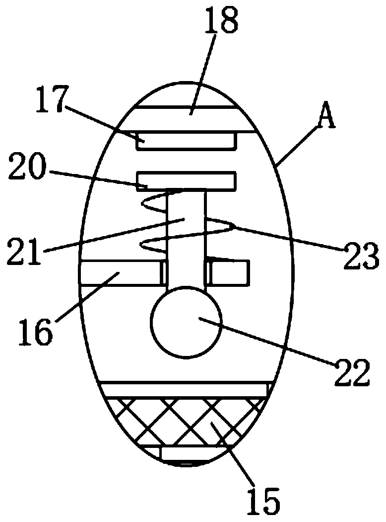
[0023] refer to Figure 2-4 The difference between the second embodiment and the first embodiment is that the rotating shaft 14 of this embodiment is fixedly sleeved with a horizontally arranged rotating rod 16, and a plurality of knocking mechanisms are arranged at equal intervals on the rotating shaft 16, and the striking mechanism includes a vertical Straight through the knocking rod 21 arranged on the rotating rod 16, and the knocking rod 21 is slidingly connected with the rotating rod 16, the lower end of the knocking rod 21 is fixedly connected with a knocking ball 22, and the upper end of the knocking rod 21 is fixedly connected with a second Two permanent magnet blocks 20, a spring 23 is sleeved on the knock rod 21, and the two ends of the spring 23 are respectively connected on the second permanent magnet block 20 and the rotating rod 16, and the upper end of the fixed plate 2 is fixedly connected with a mounting rod 19 through the fixed rod. The plate 18, the rotatin...
PUM
 Abstract
Description
Claims
Application Information
 - R&D Engineer
- R&D Manager
- IP Professional
- Industry Leading Data Capabilities
- Powerful AI technology
- Patent DNA Extraction
Browse by: Latest US Patents, China's latest patents, Technical Efficacy Thesaurus, Application Domain, Technology Topic, Popular Technical Reports.
© 2024 PatSnap. All rights reserved.Legal|Privacy policy|Modern Slavery Act Transparency Statement|Sitemap|About US| Contact US: help@patsnap.com


