
LED light-emitting device used for replacing halogen bulb

A technology of a light-emitting device and a halogen bulb, applied in the field of lighting, can solve the problems of high cost, inability to meet, and difference in light-emitting light shape, and achieve the effects of excellent effect, improved energy consumption ratio, and reduced cost.

Pending Publication Date: 2019-10-25
杭州昌松光学有限公司
View PDF0 Cites 1 Cited by
  • Summary
  • Abstract
  • Description
  • Claims
  • Application Information

AI Technical Summary

Problems solved by technology

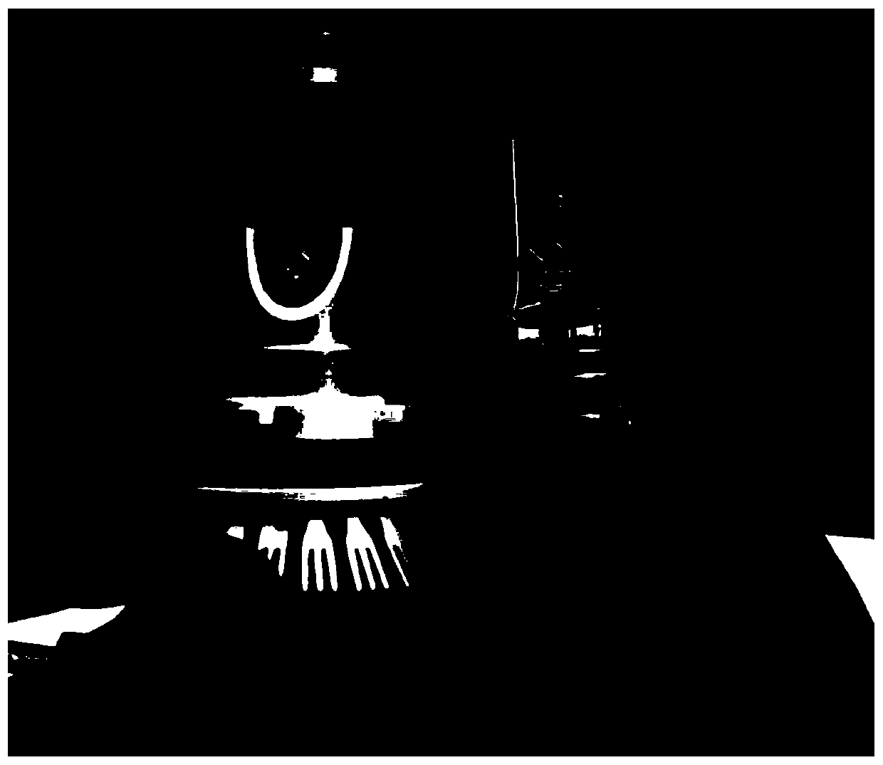
At present, there are two ways to replace LED headlights: 1. Replace the entire headlight together with the lampshade, but the cost of this solution is too high, especially for old cars, which increases the financial pressure of consumers; 2. Replace the lamp beads, but due to the halogen lamp The light shape difference with LED lights (such as figure 1 shown), LED lights ( figure 1 Left) Basically, both sides emit light, with a thick metal block in the middle; resulting in a big difference in light shape compared to halogen bulbs, so that when it is replaced into the original car headlight, no matter how it is adjusted, it cannot meet the requirements of the car's front light. Lighting standards (including Chinese GB standards, EU ECE regulations, American SAE standards, etc.)

Method used


Image

  • LED light-emitting device used for replacing halogen bulb
  • LED light-emitting device used for replacing halogen bulb
  • LED light-emitting device used for replacing halogen bulb

Examples


Embodiment Construction

[0037] The present invention will be described in detail below in conjunction with the accompanying drawings and specific embodiments, wherein the schematic embodiments and descriptions are only used to explain the present invention, but not as improper limitations to the present invention.

[0038] It should be noted that, in the case of no conflict, the embodiments in the present application and the features in the embodiments can be combined with each other. The present invention will be described in detail below with reference to the accompanying drawings and examples.

[0039] It should be noted that the terminology used here is only for describing specific implementations, and is not intended to limit the exemplary implementations according to the present application. As used herein, unless the context clearly dictates otherwise, the singular is intended to include the plural, and it should also be understood that when the terms "comprising" and / or "comprising" are used ...


PUM


Abstract

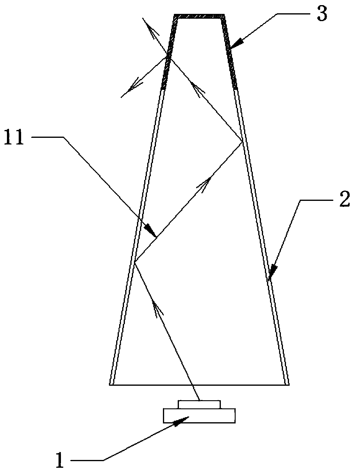
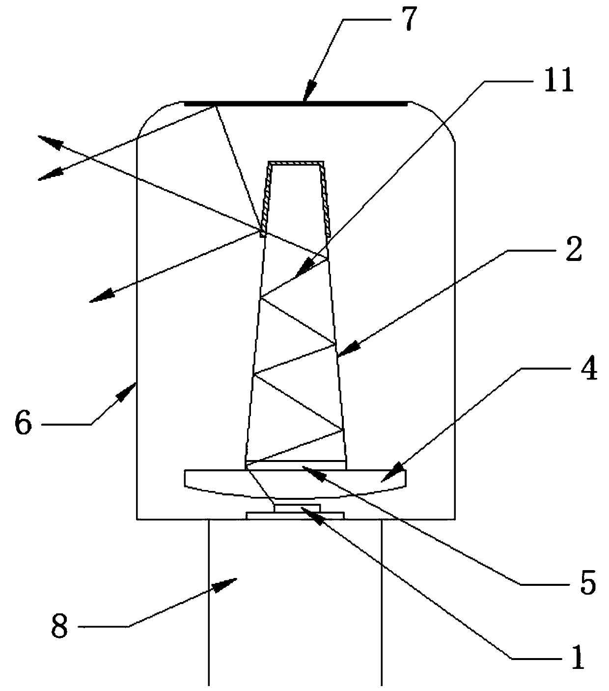
The invention discloses an LED light-emitting device used for replacing a halogen bulb. The device comprises a base, a light-emitting structure, a light-pervious cover and a reflecting film, wherein the light-emitting structure comprises an LED light source, a focusing layer, a light guide post and a diffusion layer in the sequence from bottom to top; the LED light source is fixed to the base, andthe focusing layer and the LED light source are oppositely fixed on the base; the light guide post is arranged above the focusing layer, so that light rays emitted by the LED light source irradiate in the light guide post; the light guide post is frustum-shaped, the light guide post realizes total reflection on the shot light rays; the diffusion layer covers the top end of the light guide post; the diffusion layer enables the light rays after total reflection to diffuse in the Lambertian distribution manner; and the light-emitting structure is covered by the light-pervious cover, the reflecting film is plated to the light-pervious cover, and the reflecting film is above the light-emitting structure and coaxial with the light-emitting structure. For the device, the LED light source adopting unidirectional illumination realizes the illumination range approximately according with Lambertian distribution, and the light shape is consistent with the light-emitting shape of the halogen bulb.Meanwhile, the integral cost, service life and illuminating brightness accord with the relevant requirements.

Description

technical field [0001] The invention relates to the lighting field, in particular to an LED lighting device used to replace a halogen bulb. Background technique [0002] Light-emitting diode (LED) is a commonly used light-emitting device that can efficiently convert electrical energy into light energy. Light-emitting diodes have a wide range of applications in modern society, such as lighting, flat panel displays, and medical devices. [0003] As for automotive headlights in the field of automotive lighting, low-cost halogen lamps were commonly used in the past, but halogen lamps have high energy consumption and short life, which no longer meet the current social standards. And on September 1, 2018, the European Union began to completely ban halogen bulbs, covering all non-directional low-efficiency halogen bulbs, and are no longer allowed to circulate in the UK or other regions of the EU. This means that the cars produced in EU countries bought now and in the future will a...

Claims


Application Information

Patent Timeline
IPC IPC(8): F21S41/141F21S41/24F21S41/20F21S41/30F21W102/10F21W107/10F21Y115/10
CPCF21S41/141F21S41/24F21S41/285F21S41/30F21W2102/10F21W2107/10F21Y2115/10
Inventor 岑松原董田华赵亮
Owner 杭州昌松光学有限公司
Learn More