


Quick Research
Generate reliable direction feasibility study reports for your R&D in just a few steps.

Technical Q&A
Discover and master advanced knowledge NOW. Basics, ideas, possibilities, all at once.

Find Solutions
As an expert in R&D theories, this can generate solutions to your technical problems instantly.

Evaluate Feasibility
Analyze your overall solution with one click, know your potential R&D risks in advance.

Monitor Landscape
Get weekly tech updates, stay abreast of the latest tech innovations and key insights.
An automatic cutting device for salary slips used in financial offices
An automatic cutting device and office technology, which is applied in metal processing and other directions, can solve the problems of low manual efficiency, time-consuming and laborious, etc., and achieve the effects of reducing labor and time, protecting privacy, and being easy to promote and apply
- Summary
- Abstract
- Description
- Claims
- Application Information
AI Technical Summary
Problems solved by technology
Method used
Image

Examples
Embodiment 1
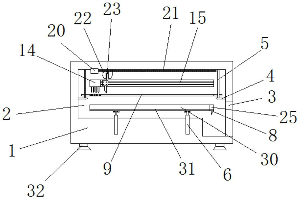
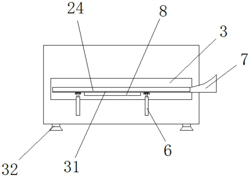
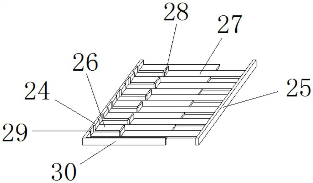
[0023] Embodiment 1: as Figure 1-7 As shown, an automatic wage slip cutting device for a financial office includes a body 1, which is characterized in that: a working chamber 2 is provided inside the body 1, and an entry and exit slot 3 is provided at the lower right side of the working chamber 2. Both sides of the middle part of the working chamber 2 are fixedly connected with a convex frame 4, and the tops of the front and rear ends of the convex frame 4 are fixedly connected with a positioning rod 5, and the top of the positioning rod 5 is fixedly connected with the top of the working chamber 2. , the positioning rod 5 is provided with four groups, the positioning rod 5 is movably connected with a backing plate 9, and the backing plate is pressed against the upper part of the paper during the rising of the bracket, and the backing plate is driven to move upward together under the action of the positioning rod , the backing plate 9 is located on the upper side of the convex...
Embodiment 2
[0024] Embodiment 2: as Figure 1-7As shown, an automatic wage slip cutting device for a financial office includes a body 1, which is characterized in that: a working chamber 2 is provided inside the body 1, and an entry and exit slot 3 is provided at the lower right side of the working chamber 2. Both sides of the middle part of the working chamber 2 are fixedly connected with a convex frame 4, and the tops of the front and rear ends of the convex frame 4 are fixedly connected with a positioning rod 5, and the top of the positioning rod 5 is fixedly connected with the top of the working chamber 2. , the positioning rod 5 is provided with four groups, the positioning rod 5 is movably connected with a backing plate 9, and the backing plate is pressed against the upper part of the paper during the rising of the bracket, and the backing plate is driven to move upward together under the action of the positioning rod , the backing plate 9 is located on the upper side of the convex ...
PUM
 Abstract
Description
Claims
Application Information
 - R&D Engineer
- R&D Manager
- IP Professional
- Industry Leading Data Capabilities
- Powerful AI technology
- Patent DNA Extraction
Browse by: Latest US Patents, China's latest patents, Technical Efficacy Thesaurus, Application Domain, Technology Topic, Popular Technical Reports.
© 2024 PatSnap. All rights reserved.Legal|Privacy policy|Modern Slavery Act Transparency Statement|Sitemap|About US| Contact US: help@patsnap.com