Long-shaft turning machine tool
A technology for turning machine tools and long shafts, which is applied to turning equipment, other manufacturing equipment/tools, tool holders, etc., and can solve problems such as lower pass rate, tool vibration, and impact on accuracy
- Summary
- Abstract
- Description
- Claims
- Application Information
AI Technical Summary
Problems solved by technology
Method used
Image

Examples
Embodiment 1
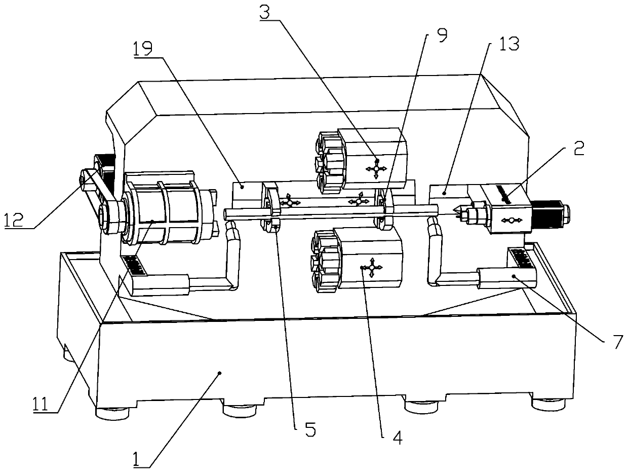
[0034] Example 1 as figure 1 As shown, a long-axis turning machine tool includes a bed 11, a column is arranged on the bed, a spindle 11 is arranged on the column, and a driving member 12 is arranged on the rear side of the column. The driving member 12 is a servo motor, and the driving member 12 is synchronously The belt drives the main shaft 11 to rotate, and the other side of the column is provided with a first movable hole 13, and a top device 2 is movable in the first movable hole 13. The top device 2 is mainly used to assist the main shaft 11 to clamp the workpiece, preventing the The end of the workpiece shakes, which affects the machining accuracy.
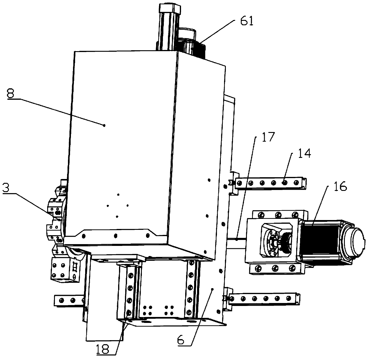
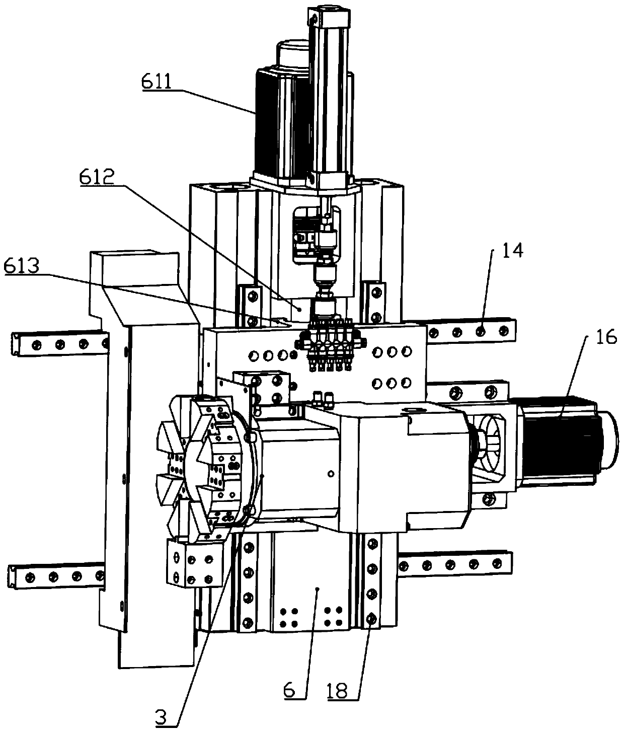
[0035] The first turret 3 and the second turret 4 are arranged on the column of the bed 1, and the first turret 3 and the second turret 4 are vertically distributed and arranged on the upper and lower sides of the clamped workpiece. The first clamping device 5 and the second clamping device 9 are also movable on the colum...
Embodiment 2
[0049] Such as Figure 11-Figure 12 As shown, other structures on the bed are the same as those in Embodiment 1, the difference is that Embodiment 2 does not have a retractable top device 2, and replaces the top device 2 with a rotating tailstock. The specific structure is as follows: one end of the column is movable Three slide rails, a rotary tailstock 111 is movably arranged on the third slide rail, and a third driving part 112 is arranged on the column, and the third driving part 112 controls the movement of the rotary tailstock 111 through a screw rod.
[0050] The rotating tailstock 111 has other functions besides ensuring the basic function of supporting the workpiece, so the rotating tailstock 111 must have a good bearing capacity, so based on this requirement, the turret seat and the turret seat handle are designed The whole body of the rotary tailstock 111 is wrapped, and only the tool part is reserved on the outside for processing the workpiece, which can greatly in...
Embodiment 3
[0052] Such as Figure 13 As shown, the technical solution of embodiment 3 is generally the same as the structure of embodiment 1 and embodiment 2, the difference is that a movable sub-spindle 135 is set on the bed, and the movement mode of the sub-spindle 135 is the same as the horizontal direction of the top device 2. The movement method is the same, both of which are driven by the motor screw to control the lateral movement of the sub-spindle 135. The application of the sub-spindle 135 is that when the processed workpiece is too thin, it can be fixed by the sub-spindle 135, which can be fixed more firmly. It looks simple and convenient.
PUM
 Abstract
Description
Claims
Application Information
 - Generate Ideas
- Intellectual Property
- Life Sciences
- Materials
- Tech Scout
- Unparalleled Data Quality
- Higher Quality Content
- 60% Fewer Hallucinations
Browse by: Latest US Patents, China's latest patents, Technical Efficacy Thesaurus, Application Domain, Technology Topic, Popular Technical Reports.
© 2025 PatSnap. All rights reserved.Legal|Privacy policy|Modern Slavery Act Transparency Statement|Sitemap|About US| Contact US: help@patsnap.com