Eureka AIR delivers breakthrough ideas for toughest innovation challenges, trusted by R&D personnel around the world.

A squeeze cleaning device for heat exchange tubes

A cleaning device and heat exchange tube technology, applied in the field of heat exchange tubes, can solve problems such as easy scratches, poor cleaning effect, and inconspicuous effect, and achieve simple and easy cleaning process, broaden cleaning methods, and apply wide range of effects

Active Publication Date: 2022-01-11
龙杰机械装备(太仓)有限公司
View PDF11 Cites 0 Cited by
  • Summary
  • Abstract
  • Description
  • Claims
  • Application Information

AI Technical Summary

Problems solved by technology

[0002] The cleaning methods of heat exchanger tubes include physical cleaning, chemical cleaning, ultrasonic cleaning, etc. In the physical cleaning method in the prior art, brushes are used to scrub the tube wall, which is easy to draw traces, and by setting spoilers in the tube, Such as the spring method, the cleaning effect is not good; in the prior art, there is a way of using extrusion to separate the dirt in the tube from the tube body under pressure, so as to realize the cleaning method of cleaning the dirt in the tube, such as in CN105066748A, by The pipe body is made of elastic and deformable material. By passing fluids with different pressures, the pipe body is expanded or contracted under pressure, so as to achieve the effect of detaching dirt; this cleaning method can effectively remove dirt, but the requirements for the pipe body More stringent, the material of the pipe body needs to be deformable within a certain range, and the deformation is more obvious. For the pipe body of the slightly deformed material, the pressure difference is only caused by passing fluids with different pressures, and the effect is poor.
In addition, there is a method of extruding the pipe body with an extrusion device to remove scale, such as in CN207703075U, through the horizontal and vertical cylinders, the pressure is applied to the plate, and then transferred to the pipe, so as to achieve scale removal. Although it can be applied to tubes with slightly harder materials, this cleaning device needs to disassemble the heat exchange tubes for extrusion cleaning
It is not practical for welded pipes, and the cleaning method is relatively simple, which can only achieve extrusion along the circumference of the pipe. The cleaning method is single and the effect is not obvious

Method used


Image

  • A squeeze cleaning device for heat exchange tubes
  • A squeeze cleaning device for heat exchange tubes
  • A squeeze cleaning device for heat exchange tubes

Examples


Embodiment Construction

[0026] The following will clearly and completely describe the technical solutions in the embodiments of the present invention with reference to the accompanying drawings in the embodiments of the present invention. Obviously, the described embodiments are only some, not all, embodiments of the present invention. Based on the embodiments of the present invention, all other embodiments obtained by persons of ordinary skill in the art without making creative efforts belong to the protection scope of the present invention.

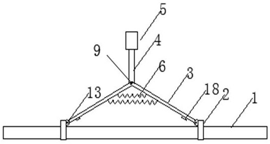
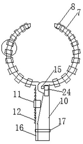
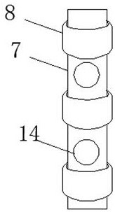
[0027] Squeeze cleaning device for heat exchange tubes, including cleaning claw 2, connecting rod 3, main rod 4, driving device 5, spring 6, main rod 4, connecting rod 3 at one end, handle 5 at the other end, connecting rod 3 and main rod 4 The connection is realized through the hinge point A9. One end of the connecting rod 3 is connected to the cleaning claw 2 through the hinge point B, and the other end is connected to the main rod 4; the cleaning claw includ...


PUM


Abstract

The invention discloses a squeeze cleaning device for heat exchange tubes. The cleaning mechanism can realize the cleaning along the axial extrusion and circumferential extrusion of the tube, broaden the cleaning mode, and can freely switch the cleaning mode. It is applied to clean the entire area along the pipe axis, and can carry out targeted cleaning for some areas that are prone to scaling and have a lot of scaling, and can adapt to different cleaning needs. The two cleaning methods correspond to two cleaning wheels for cleaning. The switching method is simple and easy to operate without affecting each other, meeting more needs and overcoming the single problem of traditional cleaning methods. The cleaning device does not require specific flexible material tubes and has a wide range of applications.

Description

technical field [0001] The invention relates to the technical field of heat exchange tubes, in particular to a squeeze cleaning device for heat exchange tubes. Background technique [0002] The cleaning methods of heat exchanger tubes include physical cleaning, chemical cleaning, ultrasonic cleaning, etc. In the physical cleaning method in the prior art, brushes are used to scrub the tube wall, which is easy to draw traces, and by setting spoilers in the tube, Such as the spring method, the cleaning effect is not good; in the prior art, there is a way of using extrusion to separate the dirt in the tube from the tube body under pressure, so as to realize the cleaning method of cleaning the dirt in the tube, such as in CN105066748A, by The pipe body is made of elastic and deformable material. By passing fluids with different pressures, the pipe body is expanded or contracted under pressure, so as to achieve the effect of detaching dirt; this cleaning method can effectively rem...

Claims


Application Information

Patent Timeline
Patent Type & Authority Patents(China)
IPC IPC(8): B08B9/023
CPCB08B9/023
Inventor 不公告发明人
Owner 龙杰机械装备(太仓)有限公司
Why Eureka
Eureka Blog
Learn More