Streamlined Insertion Pressure Compensated Emitter
A pressure compensation and sprinkler technology, applied in watering devices, gardening, agriculture, etc., can solve problems such as water head loss, achieve the effects of reducing head loss, increasing laying length, and improving conveying distance
- Summary
- Abstract
- Description
- Claims
- Application Information
AI Technical Summary
Problems solved by technology
Method used
Image

Examples
Embodiment 1
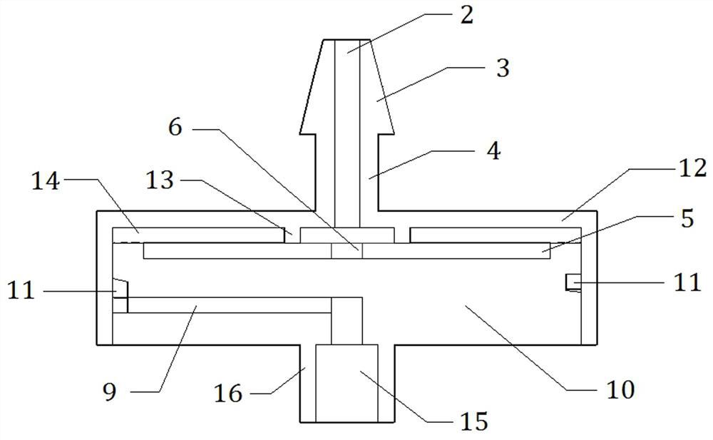
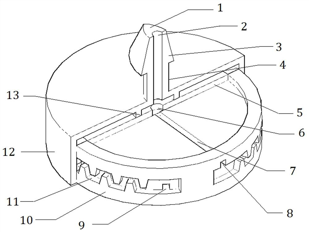
[0029] Such as figure 1 and figure 2 As shown, a streamlined plug-in pressure-compensated emitter includes an emitter plug 1 with a dripper water inlet 2, and the lower part of the emitter plug 1 is sequentially connected with a cavity shell 12 and an outer cavity 16 of the water outlet from top to bottom. A base 10 is arranged in the shell 12, a dripper chamber 14 is arranged between the upper surface of the base 10 and the chamber shell 12, and an elastic gasket 5 is arranged in the dripper chamber 14, and a compensating gasket 5 is provided on the elastic gasket 5. The gasket hole connected to the water inlet 6 of the flow channel, the labyrinth flow channel 11 is provided between the side of the base 10 and the inner wall of the cavity shell 12, the water inlet 2 of the dripper passes through the gasket hole, the water inlet 6 of the compensation flow channel and the base 10 The pressure compensation flow channel 7 opened on the top communicates with the labyrinth flow c...
Embodiment 2
[0060] Such as figure 1 with figure 2 As shown, a streamlined plug-in pressure-compensated emitter includes an emitter plug 1 with a dripper water inlet 2, and the lower part of the emitter plug 1 is connected with a chamber shell 12 and a water outlet outer chamber 16 sequentially from top to bottom. A base 10 is arranged in the shell 12, a dripper chamber 14 is arranged between the upper surface of the base 10 and the chamber shell 12, and an elastic gasket 5 is arranged in the dripper chamber 14, and a compensating gasket 5 is provided on the elastic gasket 5. The gasket hole connected to the water inlet 6 of the flow channel, the labyrinth flow channel 11 is provided between the side of the base 10 and the inner wall of the cavity shell 12, the water inlet 2 of the dripper passes through the gasket hole, the water inlet 6 of the compensation flow channel and the base 10 The pressure compensation flow channel 7 opened on the top communicates with the labyrinth flow channe...
Embodiment 3
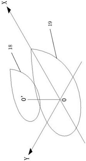
[0093] Figure 7 with Figure 8 The streamline distribution diagrams of streamlined emitter plugs and conical emitter plugs are given, from Figure 7 with Figure 8 As can be seen in the streamlined emitter plug, the flow distribution is more even. Near the water surface of the plug, there is no obvious difference in the low-velocity distribution of the two plugs, and the flow velocity of the streamlined emitter plug is slightly lower than that of the conical emitter plug. Near the outflow section of the plug, the flow velocity distribution of the two plugs is significantly different. After the water flows through the streamlined plug, it is never separated from the side wall. Near the outflow section of the plug, there is almost no low-speed vortex area. For the conical emitter plug, after the water flow reaches the outflow section, it is separated from the side wall of the plug, and an obvious low-speed vortex area appears downstream of the outflow section, resulting in a...
PUM
 Abstract
Description
Claims
Application Information
 - R&D
- Intellectual Property
- Life Sciences
- Materials
- Tech Scout
- Unparalleled Data Quality
- Higher Quality Content
- 60% Fewer Hallucinations
Browse by: Latest US Patents, China's latest patents, Technical Efficacy Thesaurus, Application Domain, Technology Topic, Popular Technical Reports.
© 2025 PatSnap. All rights reserved.Legal|Privacy policy|Modern Slavery Act Transparency Statement|Sitemap|About US| Contact US: help@patsnap.com