Al technical title is built by PatSnap Al team. It summarizes the technical point description of the patent document.
A capacitor, solid-state technology, applied in the field of solid-state capacitor impregnation, can solve the problems of incomplete impregnation of the element center, long impregnation time, and insufficient impregnation.
Active Publication Date: 2019-10-22
ZHAOQING BERYL ELECTRONICS TECH
View PDF5 Cites 3 Cited by
Summary
Abstract
Description
Claims
Application Information
AI Technical Summary
This helps you quickly interpret patents by identifying the three key elements:
Problems solved by technology
Method used
Benefits of technology
Problems solved by technology
The impregnation time of the existing process is long; on the other hand, the impregnation is not sufficient, resulting in the center of the element not being impregnated thoroughly
Method used
Image
Click on the blue label to locate the original text in one second.
Reading with bidirectional positioning of images and text.
Examples
Embodiment 1
[0028] A method for impregnating solid capacitors, comprising the steps of:
[0029] 1. Before the solid capacitor is impregnated, the preparation work is as follows:
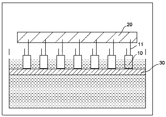
[0030] The guide pin 11 of the capacitor faces upward, and the anode guide pin 11 is spot-welded on the carrier strip 20. The consistency of the welding height must be ensured to fix multiple elements 10 on the same plane to facilitate the impregnation operation. The carrier bar 20 can be an iron bar.
[0031] Second, impregnation:
[0032] Perform the first cycle of impregnation:
[0033] (1) The tray 30 rises to suspend the elements 10, dry vacuuming to make the vacuum degree negative pressure, and the dry vacuuming time is 5-10s;
[0034] (2) Lower the tray 30 to lower the element 10 and immerse it in the impregnating solution. The impregnation depth of the element 10 is 1 / 2~2 / 3 of the height of the core package of the element 10; continue vacuuming so that the vacuum degree P1 is -30Kpa, and the holding ...
Embodiment 2
[0053] Different from Embodiment 1, in this embodiment:
[0054] During the first cycle of impregnation, the vacuum degree P1 is -40Kpa when the element is impregnated;
[0055] During the second cycle of impregnation, the vacuum degree P2 is -60Kpa when the element is impregnated;
[0056] When the third cycle of impregnation is carried out, the vacuum degree P3 is -80Kpa when the element is impregnated;
[0057] When vacuuming after impregnation, the vacuum degree P4 is -100Kpa.
Embodiment 3
[0059] Different from Embodiment 1, in this embodiment, the impregnation only includes two cycles.
PUM
Abstract
The invention discloses a solid state capacitor impregnation method, which comprises the following steps: (1) an element is suspended, dry vacuum pumping for 5 to 10 s is carried out, and a vacuum degree is made to be negative pressure; (2) the element is lowered and is immersed in an impregnation liquid, the pressure is held for 5 to 20 s, the vacuum degree is negative pressure, and the vacuum degree is equal to that in the first step; (3) the element is kept in the impregnation liquid and is deflated to a normal pressure state; (4) the above steps (1) to (3) is a cycle, the cycle is executedfor at least two times, and in the case of multiple cycles, the vacuum degree of vacuum impregnation is gradually increased; and (5) the element is suspended, dry vacuum pumping is carried out, the vacuum degree is negative pressure, and the vacuum degree is greater than any above vacuum degree. The solid state capacitor disclosed in the invention has the advantages that the impregnation time isreduced, the impregnation effects are improved, and the element center can be impregnated thoroughly.
Description
technical field [0001] The invention relates to the technical field of capacitor manufacturing, in particular to a solid capacitor impregnation method. Background technique [0002] The manufacturing method of solid capacitors generally includes cutting, nailing, impregnation, assembly, casing, aging, and characteristic testing. Among them, the existing impregnation method for solid capacitors, such as the one published in the application number 201810420475.4, named a high-voltage solid electrolytic capacitor impregnation method, when impregnating a solid capacitor, it is necessary to impregnate the core package with an impregnation solution for 10- 120 minutes. The impregnation time of the existing technology is long; on the other hand, the impregnation is insufficient, resulting in the impregnation of the center of the element is not thorough. Contents of the invention [0003] In order to make up for the defects of the prior art, the invention provides a solid capaci...
Claims
Application Information
Patent Timeline
Application Date:The date an application was filed.
Publication Date:The date a patent or application was officially published.
First Publication Date:The earliest publication date of a patent with the same application number.
Issue Date:Publication date of the patent grant document.
PCT Entry Date:The Entry date of PCT National Phase.
Estimated Expiry Date:The statutory expiry date of a patent right according to the Patent Law, and it is the longest term of protection that the patent right can achieve without the termination of the patent right due to other reasons(Term extension factor has been taken into account ).
Invalid Date:Actual expiry date is based on effective date or publication date of legal transaction data of invalid patent.