Synchronous double-switch valve plate assembly and synchronous double-switch valve core

A double switch and valve plate technology, applied in the field of valve core, can solve the problems of poor pressure resistance of the valve core, large force of the moving valve plate to break away from the fit, unable to realize the function of water supply, etc., so as to improve the sealing effect and the sealing effect. Good, easy-to-use effects

Pending Publication Date: 2019-10-22
WEIFANG CONSTOP TEMPERATURE CONTROL SANITARY WARE CO LTD
View PDF1 Cites 1 Cited by
  • Summary
  • Abstract
  • Description
  • Claims
  • Application Information

AI Technical Summary

Problems solved by technology

When the reverse water inlet is closed, that is, when 51d and 51c enter water, the top surfaces of 42a and 42b will be affected by the pressure of the water inlet, and the top surfaces of 42a and 42b are much larger than the cross-sectional area of ​​the water inlet and outlet holes, so at this time the valve Core pressure resistance is poor
This kind of spool has good pressure resistance only when water is flowing in the forward direction, and the pressure resistance of the spool is poor when the water is flowing in the reverse direction
[0008] At the same time, if the adjacent water enters, the two adjacent water inlet and outlet holes are respectively connected with the two water inlet pipes. When the valve core is in the closed state, there must be a top surface of the water tank that is affected by the water inlet pressure. At this time The moving valve plate is subject to a large force of detachment from the fixed valve plate, and the overall pressure resistance of the valve core is poor. When the water pressure is high, the valve core will burst open, and the water filling function cannot be realized.

Method used


Image

  • Synchronous double-switch valve plate assembly and synchronous double-switch valve core
  • Synchronous double-switch valve plate assembly and synchronous double-switch valve core
  • Synchronous double-switch valve plate assembly and synchronous double-switch valve core

Examples


Embodiment 1

[0057] Example one, a synchronous dual-switch spool

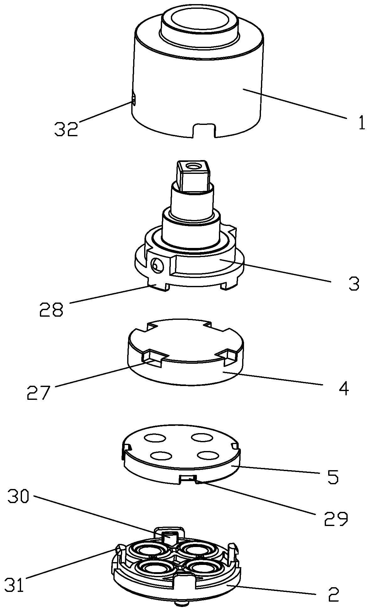
[0058] Such as figure 1 As shown, a synchronous dual-switch spool includes a housing 1 and a base 2. A dial 3 is installed between the housing 1 and the base 2, and a synchronous dual-switch valve plate assembly is installed between the dial 3 and the base 2. The synchronous double switch valve plate assembly includes a moving valve plate 4 and a fixed valve plate 5. The dial 3, the movable valve disc 4 and the fixed valve disc 5 are compressed between the housing 1 and the base 2. The lower end of the dial 3 is provided with a clamping tooth 28, and the upper end of the movable valve disc 4 is provided with a clamping groove 27. The clamping teeth 28 and the clamping groove 27 cooperate with each other to fix the movable valve disc 4 on the lower end of the dial 3 circumferentially. The upper surface of the base 2 is provided with two clamping teeth 30, and the lower end of the fixed valve disc 5 is provided with a second c...

Embodiment 2

[0066] The second embodiment, a synchronous double switch spool,

[0067] Such as Figure 10~13 As shown, the difference between the second embodiment and the first embodiment is mainly in the number of limit slots 24 on the housing 1. The number of limit slots 24 on the second embodiment is three, which are respectively the closed limit slot 36 and the full limit slot 24. The limit slot 35 and the limit slot 37 of the maximum water supply state are opened.

[0068] When in use, another adjacent water inlet and outlet through hole is connected to the water inlet pipe, such as Picture 12 As shown, the water inlet and outlet through holes 6 are connected with a water inlet pipe, the water inlet and outlet through holes 7 are connected with an outlet water channel; the water inlet and outlet through holes 29 are connected with another water inlet pipe, and the water inlet and outlet through holes 3 8 is connected to another discharge water pipeline, and the valve core is set to be in...

Embodiment 3

[0072] The third embodiment, a synchronous double switch spool,

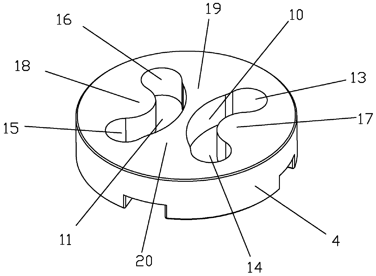
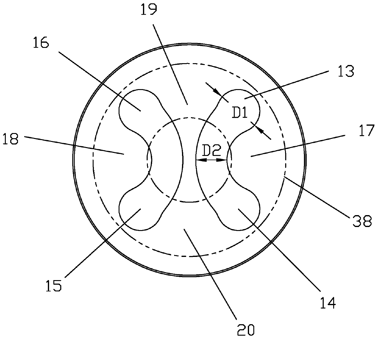
[0073] Such as Figure 14 As shown, the difference between the third embodiment and the first embodiment lies in the shape of the water passage groove on the movable valve plate 4, and the water passage groove 1 10 and the water passage groove 2 11 in the embodiment 3 are both V-shaped. Figure 15 It is a schematic diagram of the relative positions of the movable valve disc 4 and the fixed valve disc 5 when the valve core is in the closed state.

[0074] When only the switch function is needed, the two water inlet pipes are connected with the diagonally arranged water inlet and outlet through holes 6 and 8 through the inlet and outlet. The outlet pipe 1 is connected with the inlet and outlet through holes 7 and the outlet pipe 2 is connected with the inlet and outlet. The water through holes 29 are connected. Water can be discharged when the movable valve disc 4 rotates clockwise or 45 degrees counterclockwise.

[007...


PUM


Abstract

The invention discloses a synchronous double-switch valve plate assembly and a synchronous double-switch valve core. The synchronous double-switch valve plate assembly comprises a moving valve plate and a fixed valve plate, wherein the fixed valve plate is provided with a first water inlet and outlet through hole, a second water inlet and outlet through hole, a third water inlet and outlet throughhole and a fourth water inlet and outlet through hole; the lower surface of the moving valve plate is provided with a first passing water channel and a second passing water channel; the first passingwater channel comprises an A communicating end and a B communicating end; the lower surface, between the A communicating end and the B communicating end, of the moving valve plate is a first sealingsurface; the second water channel includes a C communicating end and a D communicating end; the lower surface, between the C communicating end and the D communicating end, of the moving valve plate isa second sealing surface; the lower surface, between the A communicating end and the D communicating end, of the moving valve plate is a third sealing surface; and the lower surface, between the B communicating end and the C communicating end, of the moving valve plate is a fourth sealing surface. The valve plate assembly has good pressure resistance, simple sealing structure, small torque required during rotating and low overall cost, and is convenient to popularize.

Description

Technical field [0001] The invention relates to a valve core, in particular to a synchronous double-switch valve disc assembly and a synchronous double-switch valve core. Background technique [0002] The switch spool is a device used to control the water flow. When the switch spool is closed, the water inlet pressure acts on the fixed valve plate, so that the movable valve plate receives a force that separates from the fixed valve plate under the action of water pressure. The maximum water pressure that the switch spool can withstand in the closed state is its pressure resistance. National standards have requirements for the pressure resistance of the switch spool. When the pressure resistance of the switch spool is low, if the inlet water pressure is high, the moving valve plate and the fixed valve plate will be separated, and the switch spool will burst open. The spool cannot be used. [0003] The Chinese patent with the patent number 201820148045.7 discloses a synchronous du...

Claims


Application Information

Patent Timeline
Patent Type & Authority Applications(China)
IPC IPC(8): F16K11/074F16K3/314F16K27/04F16K31/44
CPCF16K11/074F16K3/314F16K27/045F16K31/44
Inventor 薛令斌
Owner WEIFANG CONSTOP TEMPERATURE CONTROL SANITARY WARE CO LTD
Why Eureka
Try Eureka