Fabricated type building system based on inner insertion plate and end plate connection beam-column joint

A beam-column joint, prefabricated technology, applied in the direction of building, building components, building structure, etc., can solve the problems of difficult to detect on-site construction quality, low level of professionalism of construction personnel, and disadvantageous comprehensive deployment of personnel, etc., to achieve easy quality assurance. , The assembly speed is fast, and the effect of improving the clear height

Active Publication Date: 2019-10-22
BEIJING UNIV OF TECH
View PDF7 Cites 1 Cited by
  • Summary
  • Abstract
  • Description
  • Claims
  • Application Information

AI Technical Summary

Problems solved by technology

[0002] Traditional building construction methods include formwork, on-site tying of steel bars, and pouring of concrete. There are many construction steps and it is not conducive to the comprehensive deployment of personnel. The professional level of construction personnel is low, and the quality of on-site construction is difficult to detect and difficult to guarantee.
At the same time, in the construction process, a large amount of disposable consumables are required, resulting in a great waste of materials; moreover, the construction period is long and the cost of personnel wages is large

Method used


Image

  • Fabricated type building system based on inner insertion plate and end plate connection beam-column joint
  • Fabricated type building system based on inner insertion plate and end plate connection beam-column joint
  • Fabricated type building system based on inner insertion plate and end plate connection beam-column joint

Examples


Embodiment Construction

[0047]In order to make the purpose, technical solutions and advantages of the embodiments of the present invention clearer, the technical solutions in the embodiments of the present invention will be clearly and completely described below in conjunction with the drawings in the embodiments of the present invention. Obviously, the described embodiments It is a part of embodiments of the present invention, but not all embodiments. Based on the embodiments of the present invention, all other embodiments obtained by persons of ordinary skill in the art without making creative efforts belong to the protection scope of the present invention.

[0048] In the description of the present invention, it should be noted that the terms "center", "upper", "lower", "left", "right", "vertical", "horizontal", "inner", "outer" etc. The indicated orientation or positional relationship is based on the orientation or positional relationship shown in the drawings, and is only for the convenience of ...


PUM


Abstract

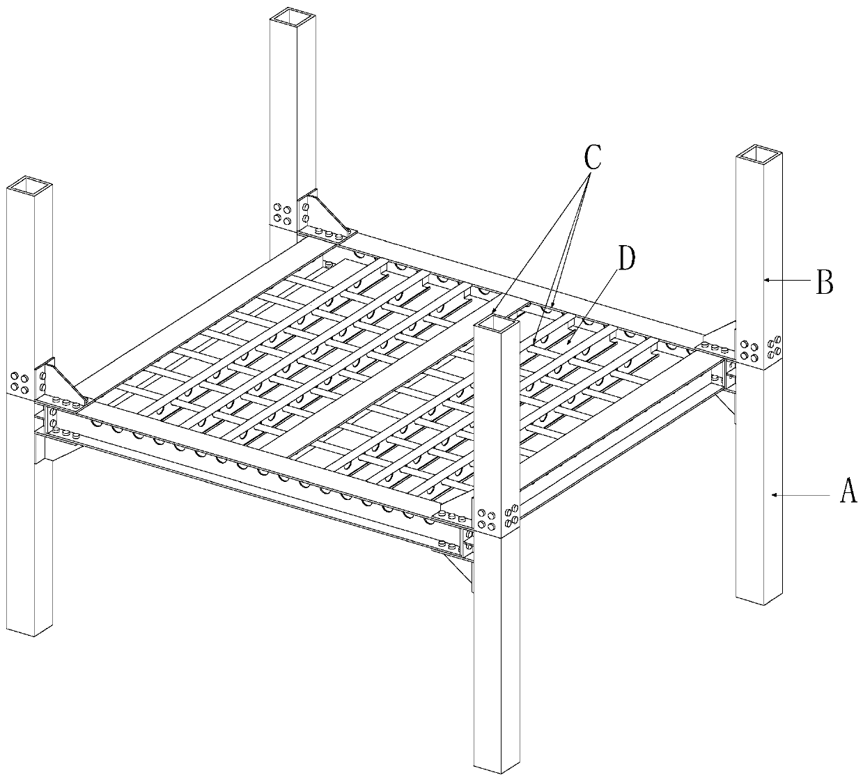
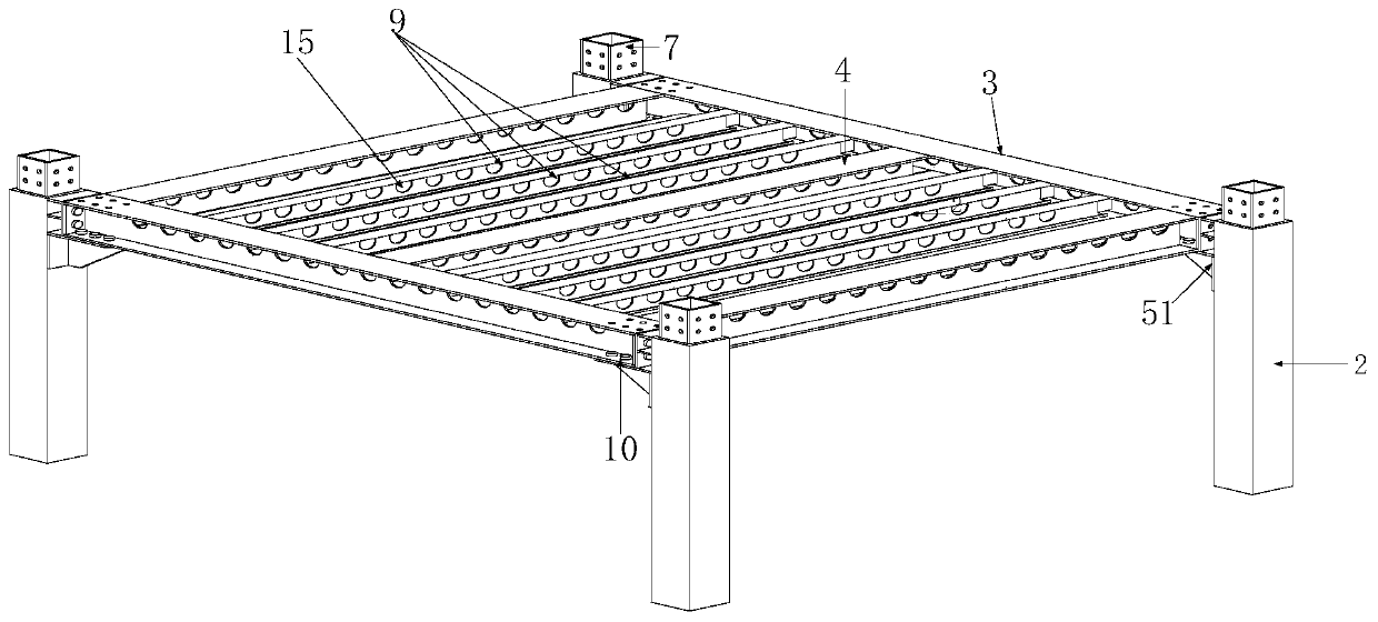
The invention discloses a fabricated type building system based on an inner insertion plate and end plate connection beam-column joint. A lower column module comprises a lower column. A first supportplate, a first end plate and an inner insertion plate are installed on each lower column. An upper column module comprises upper columns. Each upper column is provided with a second support plate. Theupper columns are correspondingly inserted into the inner insertion plates of the lower columns and are connected with the inner insertion plates through bolts. A beam module comprises main beams andauxiliary beams. Webs of the main beams and the auxiliary beams are provided with reserved wire passing holes. The two ends of the main beam are provided with second end plates. By means of connection between the first end plates and the second end plates, connection between the main beam lower flanges and the first support plates and connection between main beam upper flanges and the second support plates achieve connection of all the modules through bolts. The beams and the columns can adopt full bolt on-site assembly, the assembly speed is rapid, and the construction period is shortened. Ribbed support plates achieve the locating function on the beams and bear part of bending moment. The inner insertion plates can facilitate installation of an upper column and a lower column and lowerthe hoisting difficulty. The arranged ribbed support plates and the end plates achieve outward movement of plastic hinges. A pipeline is separated from a body structure, so that overhauling is convenient, and headroom is improved.

Description

technical field [0001] The invention belongs to the technical field of structural engineering, and relates to a prefabricated building system in which pipelines are separated, in particular to a prefabricated building system based on interlining plates and end plates connecting beam-column nodes. Background technique [0002] Traditional building construction methods include formwork, on-site binding of steel bars, and pouring of concrete. There are many construction steps and it is not conducive to the comprehensive deployment of personnel. The professional level of construction personnel is low, and the quality of on-site construction is difficult to detect and difficult to guarantee. At the same time, in the construction process, a large amount of disposable consumables are required, resulting in a great waste of materials; moreover, the construction period is long and the cost of personnel wages is large. The above problems have contributed to the development of fabricat...

Claims


Application Information

Patent Timeline
Patent Type & Authority Applications(China)
IPC IPC(8): E04B1/24E04B1/58E04B5/48
CPCE04B1/24E04B1/2403E04B5/48E04B2001/2415E04B2001/2418E04B2001/2454E04B2001/2484
Inventor 刘学春王玥
Owner BEIJING UNIV OF TECH
Why Eureka
Try Eureka