Sliding contact power supply device and power supply method for gantry crane

A technology of power supply device and gantry crane, which is applied in the direction of transportation and packaging, load hanging components, etc., can solve the problems of contact slider wear, failure of contact slider anti-corrosion protection, circuit virtual connection, etc., achieve continuous and stable power supply, and facilitate The effect of controlling the on-off of the circuit and quick lifting

Active Publication Date: 2020-05-19
LIYUE GROUP
View PDF12 Cites 0 Cited by
  • Summary
  • Abstract
  • Description
  • Claims
  • Application Information

AI Technical Summary

Problems solved by technology

This invention cannot provide anti-corrosion protection for the contact slider, and fails to solve the problem of virtual connection of the circuit caused by the wear of the contact slider

Method used


Image

  • Sliding contact power supply device and power supply method for gantry crane
  • Sliding contact power supply device and power supply method for gantry crane
  • Sliding contact power supply device and power supply method for gantry crane

Examples


specific Embodiment approach 1

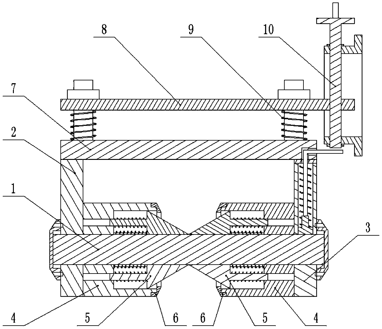
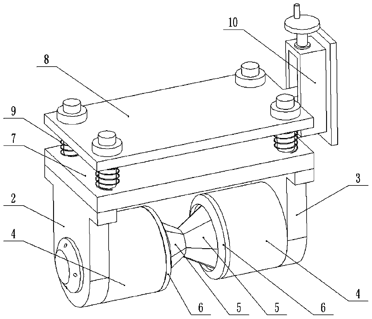
[0029] Combine below Figure 1-10 Description of this embodiment, the sliding contact power supply device and power supply method of the gantry crane, including the power connection shaft 1, the shaft frame I2, the shaft frame II3, the shaft sleeve 4, the tapered sealing part 5, the shaft sleeve end cover 6, the shaft bracket fixing part 7, The pressure plate 8, the pressure plate spring 9 and the lifting adjustment assembly 10, the left and right ends of the power-connected rotating shaft 1 are respectively rotatably connected to the axle frame I2 and the shaft frame II3, and the left and right ends of the electric-connected rotating shaft 1 are respectively fixedly connected with a shaft Sleeve 4, two shaft sleeves 4 are arranged opposite to each other, the inner ends of the two shaft sleeves 4 are slidingly connected with a plurality of conical closures 5, and the plurality of conical closures 5 are wrapped on the electric rotating shaft 1, and the shaft sleeves 4 The inner...

specific Embodiment approach 2

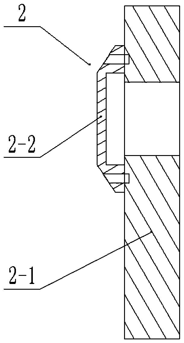
[0031] Combine below Figure 1-10 Describe this embodiment, this embodiment will further explain Embodiment 1, the axle frame I2 includes the axle frame body I2-1 and the axle frame end cover I2-2, and the axle frame end cover I2-2 is fixedly connected to the axle frame The outer end of the end cover I2-2, the shaft frame end cover I2-2 is used to seal the left end of the electric rotating shaft 1 .

specific Embodiment approach 3

[0033] Combine below Figure 1-10Describe this embodiment, this embodiment will further explain the first embodiment, the shaft frame II3 includes the shaft frame body II3-1, the shaft frame end cover II3-2, the shaft hole 3-3, the wire hole 3-4, the brush 3-5, wire 3-6, upper end cover 3-7 and brush spring 3-8, the axle frame end cover II3-2 is fixedly connected to the outer end of the axle frame body II3-1, the axle frame body II3 -1 is provided with a shaft hole 3-3 penetrating left and right, and the shaft frame body II 3-1 is provided with a vertical wire hole 3-4, and the shaft hole 3-3 communicates with the wire hole 3-4. The electric connecting shaft 1 is rotatably connected in the shaft hole 3-3, the electric brush 3-5 is slidably connected in the wire hole 3-4, the electric brush 3-5 is in contact with the electric rotating shaft 1, and the electric brush The upper end of 3-5 is fixedly connected to the wire 3-6, the upper end cover 3-7 is fixedly connected to the u...


PUM


Abstract

The invention relates to the technical field of gantry crane power supply devices, in particular to a gantry crane sliding contact power supply device and a power supply method. The device comprises an electricity connection rotary shaft, a first shaft bracket, a second shaft bracket, shaft sleeves, conical sealed parts, shaft sleeve end covers, shaft bracket fixing parts, a press plate, press plate springs and a lifting adjustment assembly. The shaft sleeves are fixedly connected to the left end and the right end of the electricity connection rotary shaft respectively. The two shaft sleeves are arranged oppositely. A plurality of conical sealed parts are in sliding connection with the inner end of each of the two shaft sleeves. The multiple conical sealed parts are arranged on the electricity connection rotary shaft in a covering manner. The inner end of each shaft sleeve is fixedly connected with a shaft sleeve end cover. The shaft bracket fixing parts are fixedly connected with theupper end of the first shaft bracket and the upper end of the second shaft bracket respectively. The press plate is connected to the upper ends of the shaft bracket fixing parts in a sliding manner. Each press plate spring is arranged between the corresponding shaft bracket fixing part and the corresponding press plate. The press plate is connected to the lifting adjustment assembly in a sliding connection manner through threads. According to the gantry crane sliding contact power supply device and the power supply method, the electricity connection rotary shaft can be prevented from being corroded by rain or sunshine, and false connection is avoided.

Description

technical field [0001] The invention relates to the technical field of power supply for gantry cranes, in particular to a sliding contact power supply device and a power supply method for gantry cranes. Background technique [0002] For example, the patent application number is CN200910301665.5, a 50T gantry crane trolley line mobile power supply device, the trolley line is suspended and fixed by the sliding contact unit, and connected to the power supply line of the gantry crane, each sliding contact unit includes a contact slider, There are three parts of the connecting piece and the suspension. The lower part of the contact slider has two sliding contact rollers with grooves on the rim. The sliding contact wires are erected in the grooves of the two sliding contact rollers. The two sliding contact rollers The wheel axle is connected between the FRP insulating plates on both sides, and the upper outer surface of the FRP insulating plate is connected to the flat iron by bol...

Claims


Application Information

Patent Timeline
Patent Type & Authority Patents(China)
IPC IPC(8): B66C13/22
CPCB66C13/22
Inventor 邵友军王辉沃凤凤吕博吴青松
Owner LIYUE GROUP
Why Eureka
Try Eureka