Deign method and design system for multi-rotor-wing unmanned aerial vehicle fire-fighting system

A multi-rotor unmanned aerial vehicle and fire-fighting system technology, which is applied in the field of aviation aircraft and high-rise building fire-fighting, can solve problems such as difficult power control, unsuitable fuel, and short life, and achieve the effect of improving application value

Pending Publication Date: 2019-10-22
陶文英
View PDF8 Cites 11 Cited by
  • Summary
  • Abstract
  • Description
  • Claims
  • Application Information

AI Technical Summary

Problems solved by technology

[0006] However, the existing technology still has the following deficiencies. As the existing fire-fighting drones generally adopt a multi-rotor platform, the power of the multi-rotor adopts a turbine engine, which can solve the requirements of loading weight and endurance time. However, the turbine engine is used The scheme has several disadvantages. One is that power control is difficult, and it is not suitable for use in places with small building distances and strong side winds. Second, it is noisy and short in life, while the electric rotor is relatively quiet and concealed. Third, there is accidental ignition of fuel. The fourth is that each unit needs to be started sequentially in operation, and the on-site preparation time is long. The fifth is that the fuel is not suitable for use in low temperature and plateau low pressure environments.

Method used


Image

  • Deign method and design system for multi-rotor-wing unmanned aerial vehicle fire-fighting system
  • Deign method and design system for multi-rotor-wing unmanned aerial vehicle fire-fighting system
  • Deign method and design system for multi-rotor-wing unmanned aerial vehicle fire-fighting system

Examples


Embodiment example

[0044] Case 1, multi-rotor aircraft 23 fire fighting operation with its own fire extinguishing agent

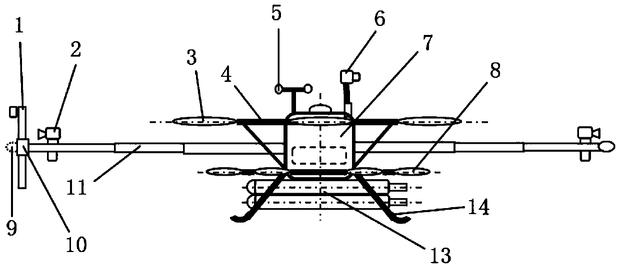
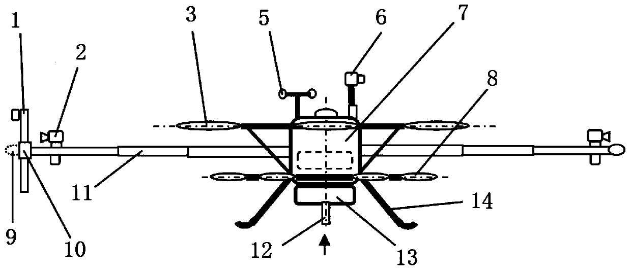
[0045] Design a multi-rotor aircraft 23 with a maximum take-off weight of 300kg and a carrying fire extinguishing agent of 100k. Suitable extinguishing agent is 7-fluoropropane, or aerosol. Airborne fire extinguishing system parameters Pressurize the 7-fluoropropane cylinder at 2.4-5.6Mpa, and pressurize the aerosol cylinder at 30Mpa. The fire extinguishing space that can be used for various types of fire fighting is about 300-500m3.

[0046] The rotor arm 4 of the multi-rotor aircraft 23 is folded and installed on the parking platform 24 of the fire-fighting power supply vehicle 21, and is fastened with a multi-claw depression bar. On the way to the high-rise fire scene, the flight parameters were set and bound according to the obtained fire scene conditions. After arriving at the scene, the hybrid truck remains on, and the firefighters unfold the fast-folding rotor arm 4...


PUM


Abstract

The invention discloses a design method and a design system for a multi-rotor-wing unmanned aerial vehicle fire-fighting system. The multi-rotor-wing unmanned aerial vehicle fire-fighting system is composed of five parts: a multi-rotor-wing aircraft, an airborne control system, an airborne fire-extinguishing load system, a fire-fighting power supply trolley and a ground controller. The multi-rotor-wing aircraft is responsible for elevating to implement a fire-fighting operation, the airborne control system is mounted in the multi-rotor-wing aircraft to control the whole course, the airborne fire-extinguishing load system implements a fire-fighting operation specifically, the fire-fighting power supply trolley is arranged on the ground to be responsible for supplying electricity and conveying an extinguishant and loading and transporting the multi-rotor-wing aircraft, and the ground controller is responsible for operation in a fire-fighting site. By adopting a mainstream fire-fighting extinguishant and putting forward various supply schemes, the multi-rotor-wing unmanned aerial vehicle fire-fighting system is suitable for a scene of the fire-fighting operation from the side face ofa high-rise building, solves the difficulty of a window-breaking operation of the fire-fighting unmanned aerial vehicle, meets the demands of scenes such as delivering survival kits, and achieves communication means such as videos, that is , a camera, needed by the fire-fighting scene.

Description

technical field [0001] The invention belongs to the field of fire protection of aviation aircraft and high-rise buildings, in particular to the engineering application field of multi-rotor unmanned aerial vehicles, and can be extended to military and maritime applications. Background technique [0002] With the increasing number of high-rise buildings in cities, fire protection and rescue have become the focus of attention. The ladders and high-pressure water guns used in traditional firefighting equipment have limited performance and cannot meet the firefighting requirements of high-rise buildings. Water as a fire extinguishing medium is more beneficial to the safety of personnel in the fire scene, but the fire extinguishing efficiency is low. If the overall plan of urban fire protection is changed, the fire protection medium and means of fire protection can be greatly improved, and the fire protection effect of high-rise buildings can be greatly improved. At present, the...

Claims


Application Information

Patent Timeline
IPC IPC(8): A62C27/00A62C37/00A62B3/00B64D1/18B64F1/12B64F3/02B60P3/11
CPCA62C27/00A62C37/00A62B3/005B64D1/18B64F1/125B64F3/02B60P3/11B64U2201/202B64U10/10B64U2101/00
Inventor 陶文英
Owner 陶文英
Why Eureka
Try Eureka