Passive cooling structure and design method for floating reactor containment

A cooling structure and containment technology, which is applied in cooling devices, reactors, nuclear power generation, etc., can solve the problems of increasing system complexity and increasing burden, so as to facilitate space allocation, reduce power consumption, and reduce the possibility of human errors sexual effect

Inactive Publication Date: 2019-10-18
NO 719 RES INST CHINA SHIPBUILDING IND
View PDF9 Cites 0 Cited by
  • Summary
  • Abstract
  • Description
  • Claims
  • Application Information

AI Technical Summary

Problems solved by technology

Based on the above problems, a series of studies have been carried out on the cooling design method of the containment of floating reactors. First, the technical methods of land-based nuclear power plants have been investigated, and it has been found that land-based nuclear power plants mostly adopt the method of containment spraying and recirculation for cooling. At this time, it is necessary to configure Two spray heat exchangers, filters and connected pipes, valves and other accessories ensure that the inlet of the spray pump in the recirculation stage cannot absorb particles and debris, and the spray pump must be equipped with a reliable power supply, which will increase the system. the complexity
In the limited space on board, if the containment cooling system design scheme for land-based nuclear power plants is adopted, the equipment layout and power supply requirements will increase the burden

Method used


Image

  • Passive cooling structure and design method for floating reactor containment
  • Passive cooling structure and design method for floating reactor containment

Examples


Embodiment Construction

[0023] In order to make the technical solutions and beneficial effects of the present invention clearer, the present invention will be further described in detail below in conjunction with the accompanying drawings and embodiments.

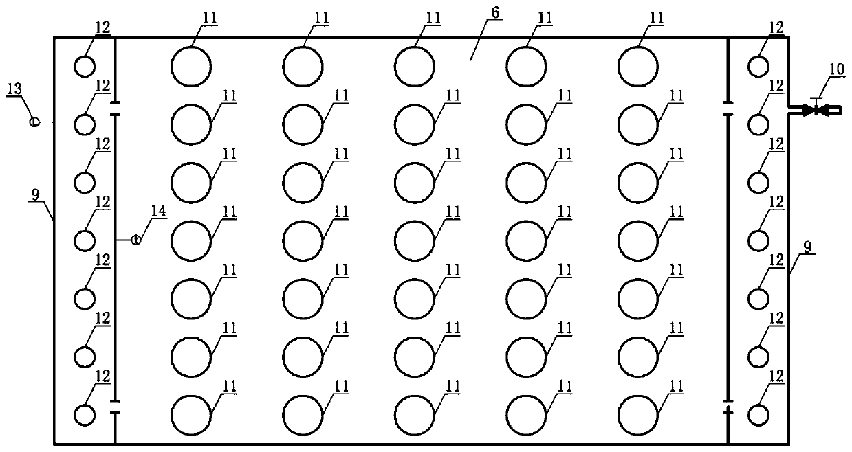
[0024] Such as figure 1 , figure 2 As shown, the present invention provides a passive cooling structure suitable for floating reactor containment,

[0025] The internal space of the containment vessel 1 is arranged with a reactor pressure vessel 2, a main pipeline 3, a steam generator 4, a pressurizer 5, and a main pump 8, wherein the reactor pressure vessel 2, the steam generator 4, the pressurizer 5, and the main pump 8 pass through The main pipelines 3 are connected to form a closed double loop system. The reactor pressure vessel 2 is used to contain the reactor core components, to ensure the integrity of the coolant pressure boundary, and to prevent the release of radioactive substances into the containment vessel. The main pipe 3 is used ...


PUM

PropertyMeasurementUnit
Spacingaaaaaaaaaa
Spacingaaaaaaaaaa

Abstract

The invention discloses a passive cooling structure and a design method for a floating reactor containment. The passive cooling structure includes a containment, which is internally equipped with a reactor pressure vessel, main pipelines, steam generators, a pressure stabilizer and main pumps, a top water tank is disposed above the containment, and is used for providing cooling function to the containment under the condition of large break loss of coolant accident and serving as a containment shielding water layer, the bottom of the containment is provided with a ballast water tank used for adjusting and balancing the hull and having the function of cooling the containment bottom, a side wall water tank for cooling the side walls of the containment and serving as a containment shielding water layer is disposed on both sides of the containment. The passive cooling structure provided by the invention not only can reduce the configuration of heat exchanger, filter, pipeline, valve and other attachments, but also has the advantages of simple structure, convenient installation and maintenance, is conducive to the spatial arrangement of equipment on board, and does not need continuous power supply, and relies on the water tank for long-term heat conduction in a passive way, thus saving a large amount of power consumption.

Description

technical field [0001] The invention relates to the technical field of special safety facilities for offshore floating reactors, in particular to a passive cooling structure suitable for floating reactor containment vessels and a design method thereof. Background technique [0002] The development of offshore floating reactors is getting faster and faster, but compared with land-based nuclear power plants, offshore floating reactors have many limiting factors, such as limited space, containment material selection, equipment weight, draft, etc. The system design of the heap is particularly critical. The safety of offshore floating reactors has always attracted everyone's attention, especially in the event of a large breach loss of water accident, a large amount of high-temperature, high-pressure media and radioactive media will be released into the containment, and the containment is responsible for containing these high-temperature, high-pressure radioactive media. , so the...

Claims


Application Information

Patent Timeline
IPC IPC(8): G21C15/18G21C11/04
CPCG21C11/04G21C15/18Y02E30/30
Inventor 雷斌乐方愿刘建阁徐广展刘斯亮刘佳张晓辉
Owner NO 719 RES INST CHINA SHIPBUILDING IND
Why Eureka
Try Eureka