
A software defined lighting system

A software-defined and lighting technology, applied in general control systems, control/regulation systems, light sources, etc., can solve problems such as poor user experience, achieve intelligent lighting, save power consumption, and save bulb wiring

Inactive Publication Date: 2019-10-18
董贤喆
View PDF2 Cites 2 Cited by
  • Summary
  • Abstract
  • Description
  • Claims
  • Application Information

AI Technical Summary

Problems solved by technology

Although smart bulbs are electronically adjustable, customers still have to adjust all smart bulbs one by one, which creates a poor user experience

Method used


Image

  • A software defined lighting system
  • A software defined lighting system
  • A software defined lighting system

Examples


Embodiment Construction

[0046] It should be noted that components in the various figures may be shown exaggerated for the purpose of illustration and are not necessarily true to scale. In the various figures, identical or functionally identical components are assigned the same reference symbols.

[0047] In the present invention, unless otherwise specified, "arranged on", "arranged on" and "arranged on" do not exclude the presence of intermediates between the two. In addition, "arranged on or above" only means the relative positional relationship between two parts, and under certain circumstances, such as after the product direction is reversed, it can also be converted to "arranged under or below", and vice versa Of course.

[0048] In the present invention, each embodiment is only intended to illustrate the solutions of the present invention, and should not be construed as limiting.

[0049] In the present invention, unless otherwise specified, the quantifiers "a" and "an" do not exclude the scen...


PUM


Abstract

The present invention relates to a software defined lighting system based on a lighting scene, comprising: a plurality of smart bulbs having one or more adjustable control parameters, where the smartbulbs are configured to be able to communicate with a console to receive respective control parameters from the console; and the console configured to receive lighting scene information and convert the lighting scene information into control parameters of the smart bulbs. Through the lighting system, setting or adjustment of a plurality of bulbs can be rapidly and intelligently achieved, and a user does not need to set or adjust the bulbs one by one; furthermore, the lighting system is programmable, for example, software can be used to configure different settings without making hardware modifications.

Description

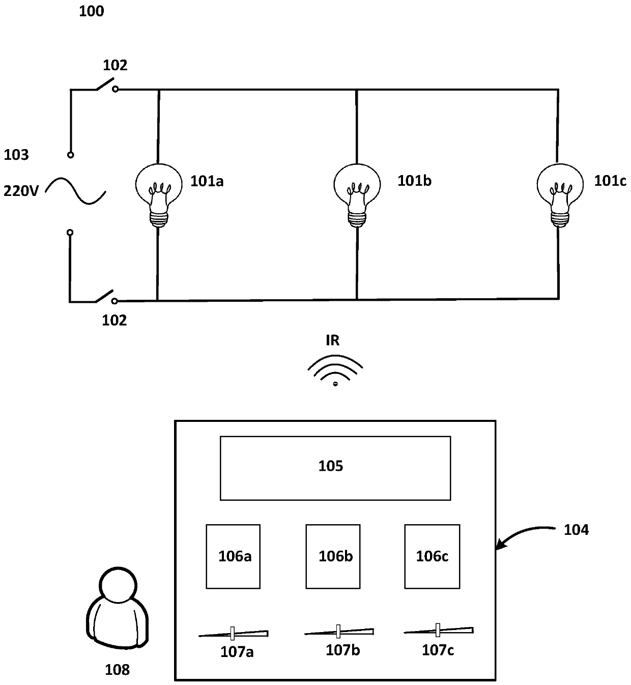
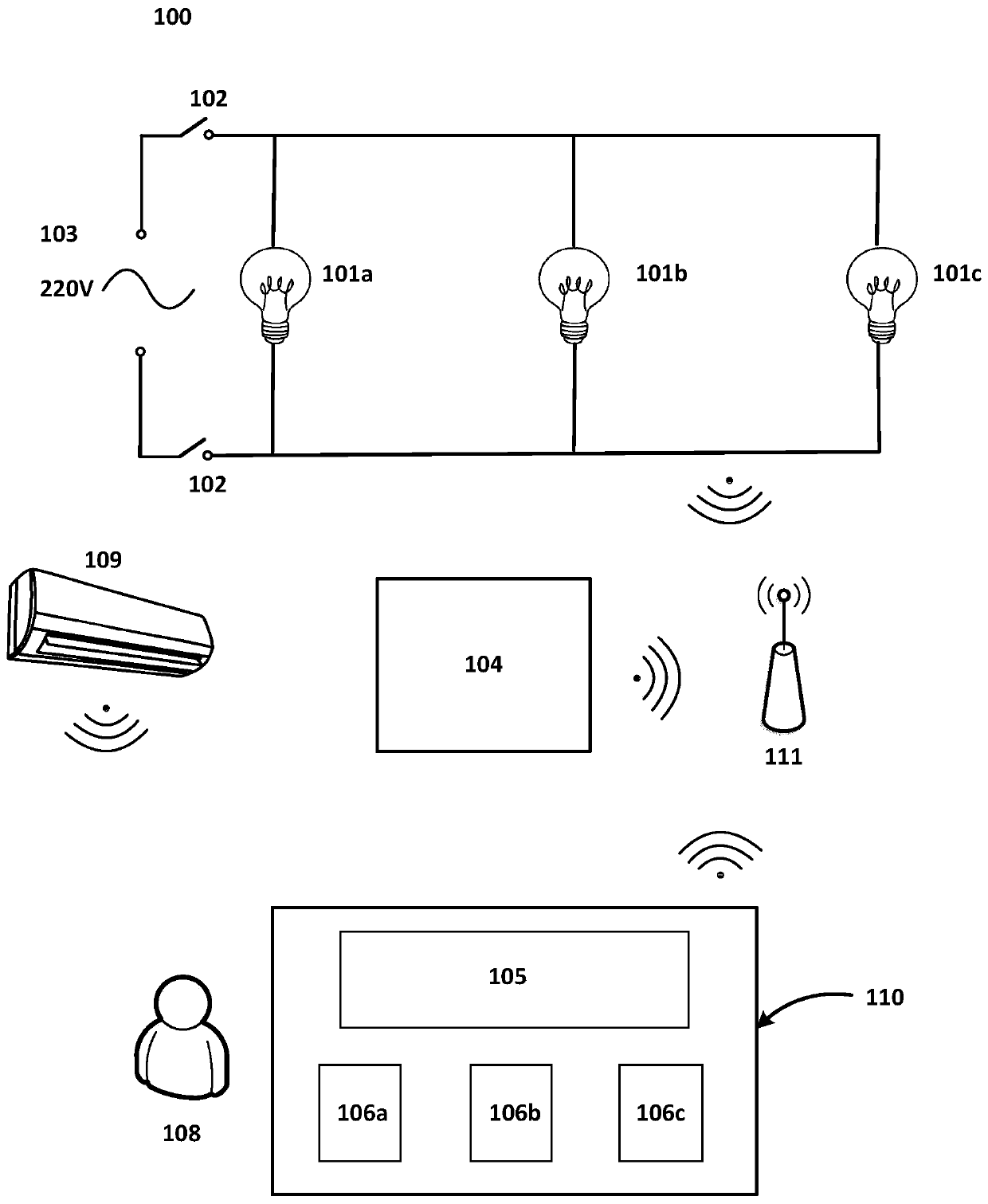
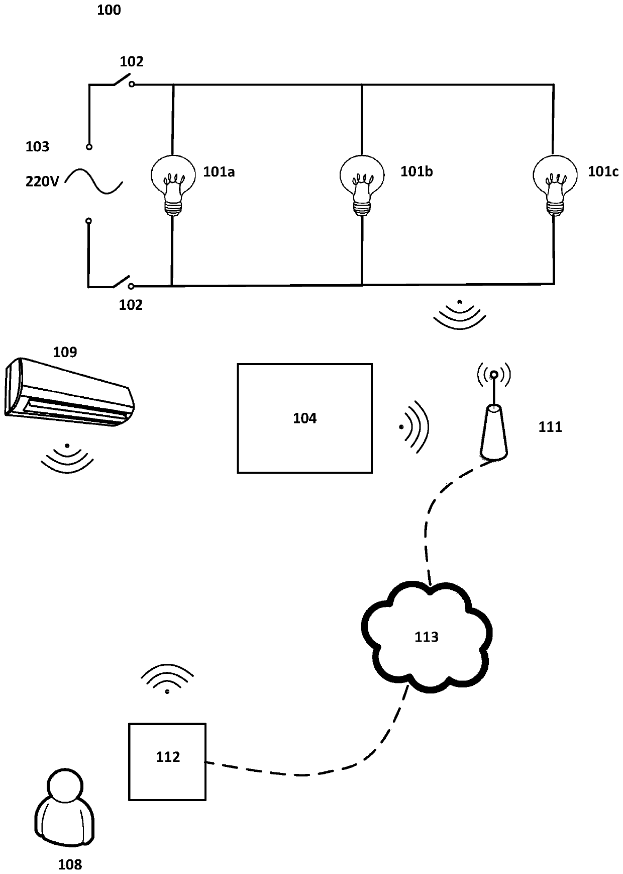
technical field [0001] The present invention generally relates to the field of smart home, and specifically relates to a software-defined lighting system based on lighting scenes. Background technique [0002] In order to adapt to different customer needs and different use occasions, residential places such as hotel rooms generally have many (such as more than 10) lighting sources (bulbs) to provide the required lighting for different positions or occasions, such as Lighting when bathing, lighting when making up, lighting when meeting guests in the room, reading lighting before going to bed, etc. These different lighting sources often have complicated electrical connections, and are generally controlled individually and individually through the room electric control panel (usually at the client's bedside and bathroom door). Such complex electrical connections not only imply complex wiring and construction costs, but also complex and expensive control systems / panels. [000...

Claims


Application Information

Patent Timeline
Patent Type & Authority Applications(China)
IPC IPC(8): G05B19/418G05B15/02G05D25/02H05B37/02
CPCG05B19/418G05B15/02G05D25/02G05B2219/2642H05B47/10H05B47/19Y02B20/40
Inventor 董贤喆
Owner 董贤喆
Learn More