
Toner feeding barrel with toner feeding holes and toner feeding box

A technology of powder buckets and powder boxes, which is applied in the direction of electric recording technology using charge patterns, equipment and instruments using charge pattern electric recording technology, etc. It can solve the problems of low powder filling efficiency and cumbersome operation process, and achieve the goal of adding powder high efficiency effect

Inactive Publication Date: 2019-10-18
佛山普瑞威尔科技有限公司
View PDF11 Cites 2 Cited by
  • Summary
  • Abstract
  • Description
  • Claims
  • Application Information

AI Technical Summary

Problems solved by technology

[0002] The HP laser printer adopts flash charging technology to add powder. The powder injection port of HP 1005w is located on the right side of the fuselage. You only need to open the cover above the powder injection port to fill the powder, and insert the powder container into the powder injection port. There is a chip at the insertion end of the toner box that is electrically connected to the printer, and the entire process of toner supply can be completed within a few seconds. The hole on the printer is punched into the toner box of the printer, so that the toner box can be reused, but the toner filling box in the prior art still has certain defects. When the powder in the toner box is used outside, it needs to be disassembled The upper cover and the piston then fill the powder bucket with powder, and the upper cover needs to be disassembled. The operation process is cumbersome and the powder filling efficiency is low.

Method used

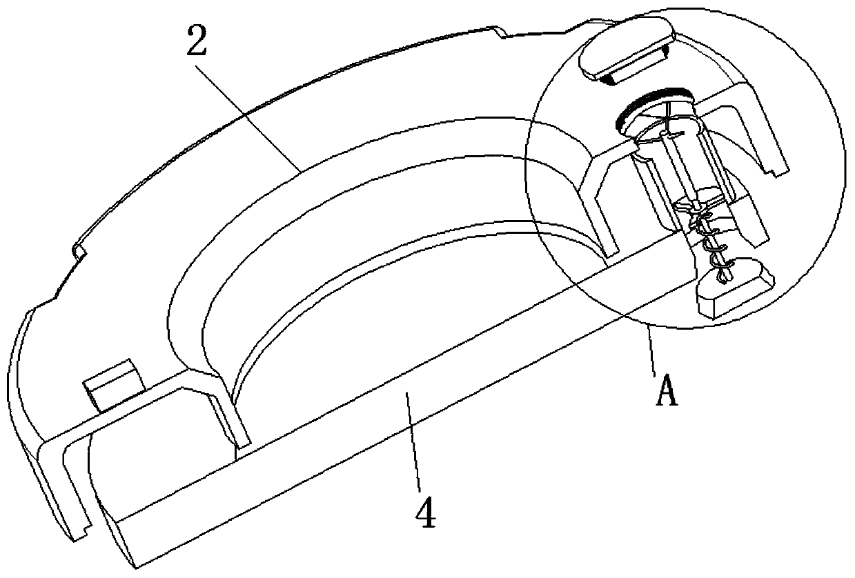
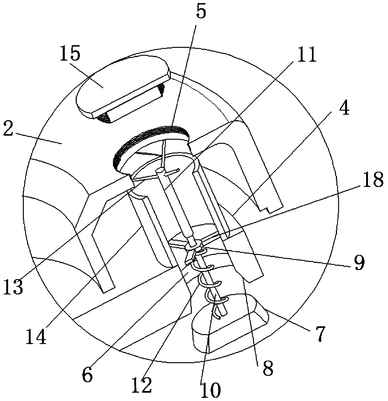
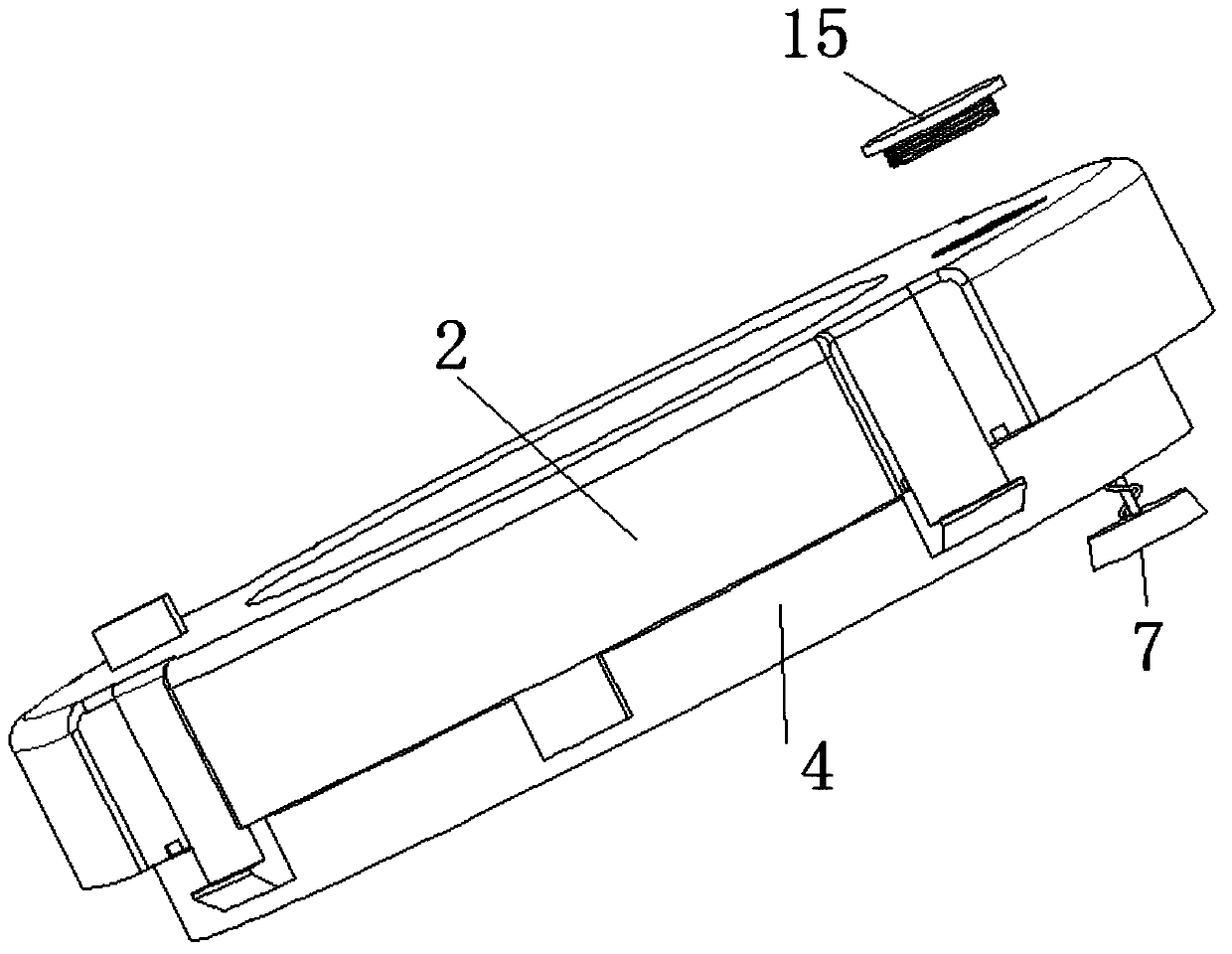

Image

  • Toner feeding barrel with toner feeding holes and toner feeding box
  • Toner feeding barrel with toner feeding holes and toner feeding box
  • Toner feeding barrel with toner feeding holes and toner feeding box

Examples


Embodiment Construction

[0040] The following will clearly and completely describe the technical solutions in the embodiments of the present invention with reference to the accompanying drawings in the embodiments of the present invention. Obviously, the described embodiments are only some, not all, embodiments of the present invention.

[0041] In describing the present invention, it should be understood that the terms "upper", "lower", "front", "rear", "left", "right", "top", "bottom", "inner", " The orientation or positional relationship indicated by "outside", etc. is based on the orientation or positional relationship shown in the drawings, and is only for the convenience of describing the present invention and simplifying the description, rather than indicating or implying that the referred device or element must have a specific orientation, so as to Specific orientation configurations and operations, therefore, are not to be construed as limitations on the invention.

[0042] It should be noted...


PUM


Abstract

The invention discloses a toner feeding barrel with toner feeding holes and a toner feeding box and belongs to the field of printer toner feeding boxes. The toner feeding barrel with the toner feedingholes comprises a toner barrel. The toner feeding barrel further comprises an upper cover, a piston, a first toner feeding hole, a second toner feeding hole, a conical sealing plug, and a conical opening; the upper cover is connected with the upper end of the toner barrel; the piston is slidingly connected into the toner barrel in a sealed manner; the first toner feeding hole is formed in the upper cover; the second toner feeding hole is formed in the piston and is corresponding to the first toner feeding hole; the conical sealing plug is arranged at the lower end of the second toner feeding hole; and the conical opening is formed in the lower end of the second toner feeding hole and is corresponding to the conical sealing plug. According to the toner feeding barrel with the toner feeding holes of the invention adopted, the conduction of the toner barrel can be realized through the first toner feeding hole and the second toner feeding hole, so that toner feeding can be carried out;after the toner feeding is completed, resetting can be performed; the conical sealing plug can be tightly attached onto the conical opening under the action of a tension spring so as to plug the conical opening; and toner feeding can be carried out without disassembling the upper cover required, and therefore, toner feeding efficiency is high.

Description

technical field [0001] The invention relates to the technical field of a powder filling box for a printer, in particular to a powder filling bucket and a powder filling box with powder filling holes. Background technique [0002] The HP laser printer adopts flash charging technology to add powder. The powder injection port of HP 1005w is located on the right side of the fuselage. You only need to open the cover above the powder injection port to fill the powder, and insert the powder container into the powder injection port. There is a chip at the insertion end of the toner box that is electrically connected to the printer, and the entire process of toner supply can be completed within a few seconds. The hole on the printer is punched into the toner box of the printer, so that the toner box can be reused, but the toner filling box in the prior art still has certain defects. When the powder in the toner box is used outside, it needs to be disassembled The upper cover and the...

Claims


Application Information

Patent Timeline
IPC IPC(8): G03G15/08
CPCG03G15/0865
Inventor 周露露
Owner 佛山普瑞威尔科技有限公司
Learn More