
An experimental device for testing the non-equilibrium gas-liquid two-phase pipeline flow of liquefied natural gas

A technology for liquefied natural gas and testing pipelines, which is applied in the field of experimental devices for testing the non-equilibrium gas-liquid two-phase pipeline flow of liquefied natural gas, which can solve the problem of inability to simulate the flow state of low-temperature LNG and the difficulty in obtaining the non-equilibrium gas-liquid phase transition parameters of LNG. The experimental parameters of phase pipe flow, the inability to simulate and control the large temperature difference between the LNG pipeline and the environment, etc.

Active Publication Date: 2020-11-24
SOUTHWEST PETROLEUM UNIV
View PDF10 Cites 0 Cited by
  • Summary
  • Abstract
  • Description
  • Claims
  • Application Information

AI Technical Summary

Problems solved by technology

However, at present, the experimental tests for the non-equilibrium gas-liquid phase transition of oil and gas media are mainly carried out in reactors, and the experimental media are mainly normal temperature liquids such as crude oil and natural gas; such experimental devices cannot simulate the transportation of low-temperature LNG. The flow state in the pipeline cannot simulate and control the large temperature difference between the LNG pipeline and the environment, so it is difficult to obtain the experimental parameters needed to study the non-equilibrium gas-liquid phase transition parameters of LNG and the gas-liquid two-phase pipeline flow

Method used


Image

  • An experimental device for testing the non-equilibrium gas-liquid two-phase pipeline flow of liquefied natural gas

Examples


specific Embodiment approach

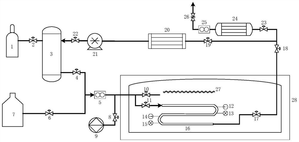
[0018] The first step: close the first valve 2, the second valve 4, the third valve 6, the eighth valve 18, the ninth valve 19, the tenth valve 22, the eleventh valve 23, the safety valve 26, and open the fourth valve 8 , the fifth valve 10, the sixth valve 11, the seventh valve 17;

[0019] Second step: open the vacuum pump 9, vacuumize the experimental test pipeline 16 and the vacuum dewar 28, and measure the vacuum pressure with the first pressure gauge 13 and the second pressure gauge 15;

[0020] Step 3: When the vacuum pressure reaches 0.03MPa, the vacuuming ends, and the vacuum pump 9 and the fourth valve 8 are closed;

[0021] The fourth step: open the third valve 6, the eighth valve 18, the eleventh valve 23, the safety valve 26, precool the experimental test pipeline 16 and the vacuum dewar 28, and measure it by the first thermometer 12 and the second thermometer 14 Experimental testing pipeline 16 internal and external wall temperature;

[0022] Step 5: When the t...


PUM


Abstract

The invention provides an experimental device for testing non-equilibrium gas-liquid two-phase pipeline flow of liquefied natural gas. The device is composed of a high pressure nitrogen gas cylinder,a liquefied natural gas storage tank, a flow meter, a liquid nitrogen container, a valve, a thermometer, a pressure gage, an experimental testing pipeline, a pressure regulating reaction container, aconstant pressure pump, a liquefied natural gas vaporizer, a condenser, a low temperature pump, an electric heating device, a vacuum dewar and a vacuum pump. Pressures in a test pipeline and the pressure regulating reaction container are controlled by changing the opening of a pressure reducing valve and the rotating speed of the constant pressure pump, and temperatures of the experimental test pipeline and the pressure regulating reaction container are controlled by changing the power of the electric heating device and the liquid nitrogen injection rate, so that gas-liquid phase change and gas-liquid two phase flow of a liquefied natural gas conveying pipeline and an external environment in a large temperature difference condition are tested. The experimental device provided by the invention overcomes the defect that an existing device cannot test the gas-liquid phase change rate and gas-liquid two phase flow of low temperature LNG in a pipeline flowing process and has the function ofcyclically using the liquefied natural gas, so that the experimental cost is lowered.

Description

technical field [0001] The invention relates to an experimental device for testing the non-equilibrium gas-liquid two-phase pipeline flow of liquefied natural gas, and relates to the fields of storage, transportation and pipeline transportation of liquefied natural gas. Background technique [0002] Liquefied Natural Gas (LNG) is a liquid mixture formed by cooling natural gas to -162°C under normal pressure. The main components include methane and a small amount of light hydrocarbon components such as ethane and propane. Pipelines play a very important role in the processing and transportation of LNG. In order to ensure that LNG is in a liquid state in the pipeline, the temperature in the pipeline is maintained below -162°C, and the ambient temperature around the pipeline is generally atmospheric temperature, so the difference between the LNG delivery temperature and the ambient temperature can be as high as 170°C or more . Under such special conditions of large temperatur...

Claims


Application Information

Patent Timeline
Patent Type & Authority Patents(China)
IPC IPC(8): F17C5/02F17C13/00F17C13/04F17D1/02F17D3/01
CPCF17C5/02F17C13/00F17C13/04F17C2221/033F17D1/02F17D3/01
Inventor 贾文龙罗强吴瑕杨帆李长俊张员瑞
Owner SOUTHWEST PETROLEUM UNIV
Learn More