
Micro semi-automatic ball valve

A semi-automatic, ball valve technology, used in valve details, valve devices, engine components, etc., can solve problems such as dependence and short service life, and achieve the effects of sensitive response, long service life and simple structure

Inactive Publication Date: 2019-10-18
孙祥
View PDF0 Cites 0 Cited by
  • Summary
  • Abstract
  • Description
  • Claims
  • Application Information

AI Technical Summary

Problems solved by technology

The defect of this common cryogenic valve is: due to the long-term operation at low temperature, the main seal of the valve body only depends on the pre-tightened wound gasket seal, the service life is short, and the sealing packing at the top of the valve stem is in a high and low temperature alternating state for a long time , the same short service life
And the ball valve is a floating ball design, only suitable for small diameter low pressure valves
The technicians of scientific research units and enterprises are constantly exploring and researching, hoping to develop a ball valve with superior performance. Although some progress has been made, there are still technical problems that have not been overcome in practical application.

Method used


Image

  • Micro semi-automatic ball valve

Examples


Embodiment Construction

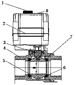
[0008] A miniature semi-automatic ball valve, the ball valve includes a handwheel 1, an actuator 2, a valve stem 3, a valve body 4, a ball core 5, a valve seat 6, a sealing ring 7 and an observation window 8, and the valve body 4 is set On the top of the ball valve, the valve body 4 includes symmetrical inlets and outlets, the valve seat 6 is arranged in the middle of the valve body 4, the ball core is installed on the valve seat 6, and the valve stem 3 is vertically arranged in the valve body 4, one end of the valve stem 3 is connected to the ball core 5, and the other end is connected to the output shaft of the actuator 2, and the actuator 2 is arranged on the upper part of the valve body 4. The hand wheel 1 is connected to the upper part of the actuator 2, the top of the actuator 2 is provided with a plurality of observation windows 8, and the valve body 4 is provided with a sealing ring 7.

[0009] The above embodiments are only used to illustrate the present invention rat...


PUM


Abstract

The invention relates to a micro semi-automatic ball valve which comprises a hand wheel, an actuator, a valve rod, a valve body, a ball core, a valve seat, a seal ring and observation windows. The valve body is arranged on the top part of the ball valve; the valve body comprises an inlet and an outlet symmetrical left and right; the valve seat is arranged in the middle in the valve body; the ballcore is arranged on the valve seat; the valve rod is vertically arranged in the valve body; one end of the valve rod is connected onto the ball core; the other end of the valve rod is connected onto an output shaft of the actuator; the actuator is arranged on the upper part of the valve body; the hand wheel is connected to the upper part of the actuator; the multiple observation windows are arranged on the top part of the actuator; and the seal ring is arranged in the valve body. The micro semi-automatic ball valve provided by the invention is simple in structure, environmental-friendly, smallin water discharge, good in sealing performance, zero-leakage, wide in application range, wide in appropriate temperature range, sensitive in reaction, stable in working, and long in service life.

Description

technical field [0001] The invention relates to a valve, in particular to a miniature semi-automatic ball valve. Background technique [0002] At present, ordinary cryogenic ball valves generally adopt a one-way sealing structure, and a pressure relief hole is provided on the side wall of the ball corresponding to the upstream end of the valve body, so that when the ball is closed, the valve chamber is always connected with the upstream high-pressure medium to avoid accidents caused by low-temperature gasification of the medium. The stem part is set with a long neck structure, so that the sealing packing is away from the end of the ball, so as to ensure the sealing of the stem during the long-term switching process of the valve. The defect of this common cryogenic valve is: due to the long-term operation at low temperature, the main seal of the valve body only depends on the pre-tightened wound gasket seal, the service life is short, and the sealing packing at the top of the...

Claims


Application Information

Patent Timeline
Patent Type & Authority Applications(China)
IPC IPC(8): F16K5/06F16K5/20F16K37/00F16K31/60
CPCF16K5/06F16K5/20F16K31/60F16K37/00
Inventor 孙祥
Owner 孙祥
Learn More