
Sludge drying carbonization drying furnace heating control system

A sludge drying and control system technology, applied in fixed carbonization furnaces, dehydration/drying/thickened sludge treatment, chemical instruments and methods, etc. The problem of heat loss in the furnace and carbonization furnace can be solved to achieve the effect of controlling pollution, reducing production costs and reducing exhaust gas emissions

Pending Publication Date: 2019-10-18
安徽省通源环境节能股份有限公司
View PDF0 Cites 4 Cited by
  • Summary
  • Abstract
  • Description
  • Claims
  • Application Information

AI Technical Summary

Problems solved by technology

[0002] Most of the existing drying furnaces and carbonization furnaces adopt separate layouts, which cannot be integrated into the same system for collaborative use. At the same time, there is a large amount of heat loss during the operation of the drying furnace and carbonization furnace. Since the integrated integration cannot be realized, As a result, the heat exhausted by each furnace body cannot be shared reasonably, and the exhausted waste cannot be reasonably disposed of. The above problems are all defects in the prior art. In order to overcome the above defects, continue to look for a more efficient equipment system

Method used


Image

  • Sludge drying carbonization drying furnace heating control system
  • Sludge drying carbonization drying furnace heating control system

Examples


Embodiment Construction

[0024] The present invention will be further described below in conjunction with accompanying drawing:

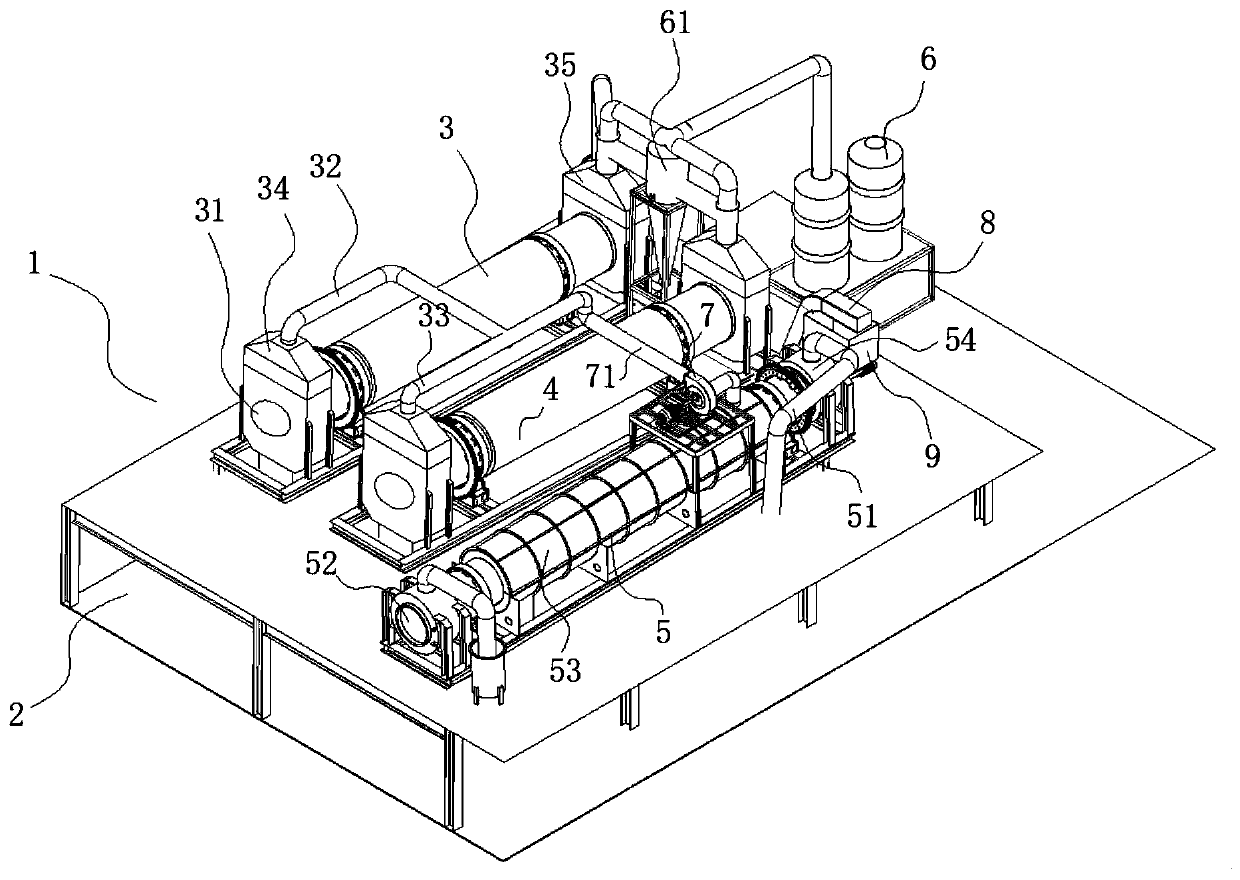
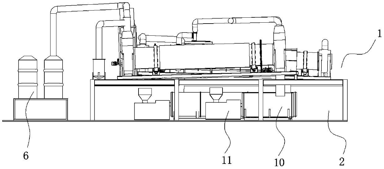
[0025] Such as Figure 1-2 The heat supply control system for sludge drying and carbonization drying furnace shown in the figure includes a treatment system 1 and a heating system 2 arranged in upper and lower layers. Through layered settings, the space utilization rate can be effectively improved and land resources can be saved. The treatment system 1 includes a first drying furnace 3 , a second drying furnace 4 and a carbonization furnace 5 , and the heating system 2 includes a second combustion chamber 10 and a biomass burner 11 .

[0026] The first drying furnace 3 and the second drying furnace 4 are arranged side by side, and are communicated with a pipeline for internal circulation of hot gas at their respective feeding bins 34 ports. The pipeline branch line 1 32 on the carbonization furnace 5 is connected to the pipeline branch line 2 33 on the drying furnace 2 4. ...


PUM


Abstract

The invention discloses a sludge drying carbonization drying furnace heating control system, which comprises a processing system and a heating system which are arranged in an upper and lower layered mode. The processing system internally comprises a first drying furnace, a second drying furnace, and a carbonization furnace, the heating system comprises a second combustion chamber and a biomass burner, the carbonization furnace communicates with a second pipeline for hot gas internal circulation, the second pipeline communicates with a first pipeline, and the second pipeline is provided with afan group used for controlling the flow rate of hot gas in the pipeline and forming a negative pressure environment for hot gas internal circulation, the carbonization furnace is provided with a looppipe communicating with the heating system, and the end opening parts of material discharging bins of the first drying furnace and the second drying furnace communicate with a deaeration device used for exhaust gas treatment. According to the sludge drying carbonization drying furnace heating control system, the negative pressure environment in the pipeline is generated through the fan group, thusrecycling of heat energy is realized, exhaust gas emission is reduced while the energy consumption loss is lowered, improving the production efficiency of an enterprise is improved, and the production cost is lowered.

Description

technical field [0001] The invention relates to the technical field of drying and carbonization, in particular to a heat supply control system for a sludge drying and carbonization drying furnace. Background technique [0002] Most of the existing drying furnaces and carbonization furnaces adopt separate layouts, which cannot be integrated into the same system for collaborative use. At the same time, there is a large amount of heat loss during the operation of the drying furnace and carbonization furnace. Since the integrated integration cannot be realized, As a result, the heat exhausted by each furnace body cannot be shared reasonably, and the exhausted waste cannot be reasonably disposed of. The above problems are all defects in the prior art. In order to overcome the above defects, continue to search for a more efficient equipment system. Contents of the invention [0003] The object of the present invention is to provide a heat supply control system for sludge drying ...

Claims


Application Information

Patent Timeline
Patent Type & Authority Applications(China)
IPC IPC(8): C02F11/13C10B1/06B01D53/14B01D47/06
CPCC02F11/13C10B1/06B01D53/14B01D47/06
Inventor 杨明陈斌邹献余陈杨杨夏坤高岭贺前锋杨见博王猛汪向阳
Owner 安徽省通源环境节能股份有限公司
Learn More