
C-column reinforcing plate connecting structure

A technology of connecting structures and reinforcing plates, applied in the field of auto parts, can solve the problems of local stress concentration of the body, unclear transmission path, poor passenger experience, etc., and achieve the effect of preventing local stress concentration, avoiding body cracking, and improving torsional stiffness.

Pending Publication Date: 2019-10-15
CHERY AUTOMOBILE CO LTD
View PDF6 Cites 9 Cited by
  • Summary
  • Abstract
  • Description
  • Claims
  • Application Information

AI Technical Summary

Problems solved by technology

In this structure, the C-pillar reinforcement plate is not connected to the rear wheelhouse inner panel reinforcement plate. The force transmission path in this structure is not clear, which may easily cause local stress concentration in the body, resulting in cracking. In addition, the body has a strong sense of bumps and poor passenger experience. Difference

Method used


Image

  • C-column reinforcing plate connecting structure
  • C-column reinforcing plate connecting structure
  • C-column reinforcing plate connecting structure

Examples


Embodiment Construction

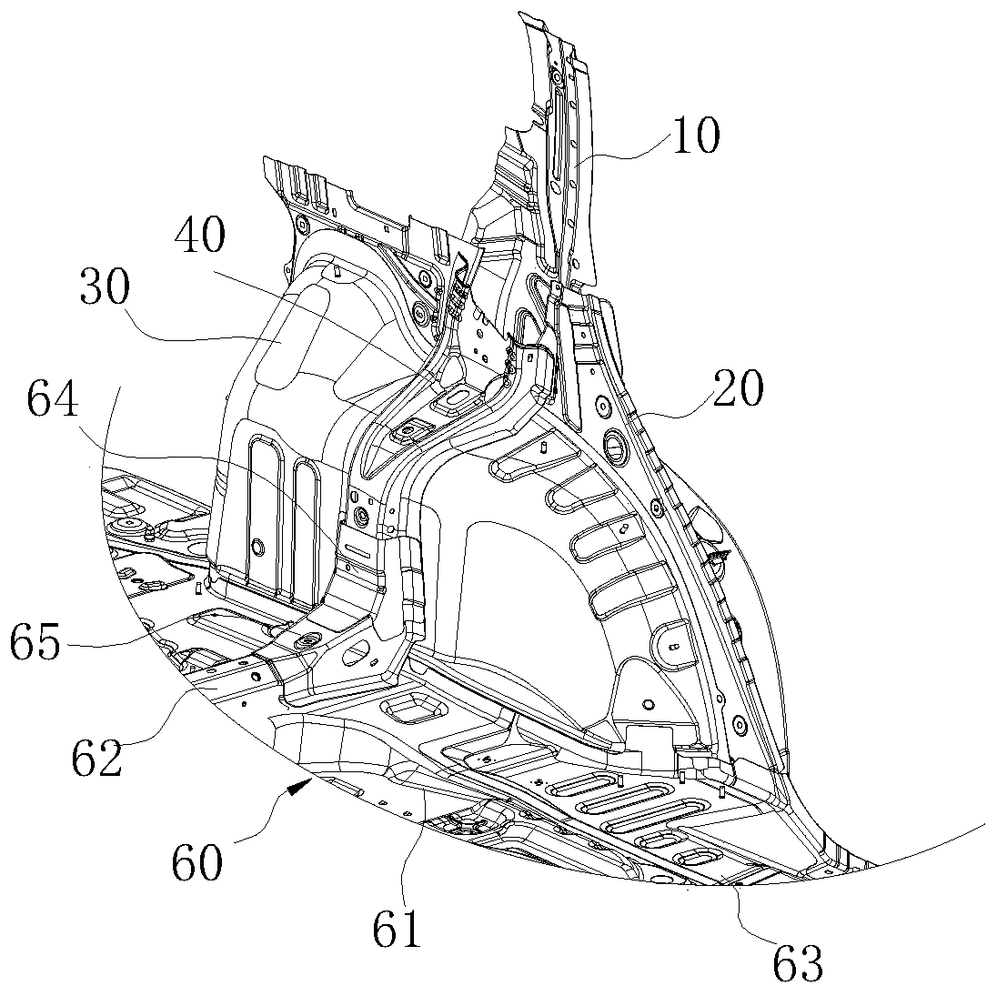
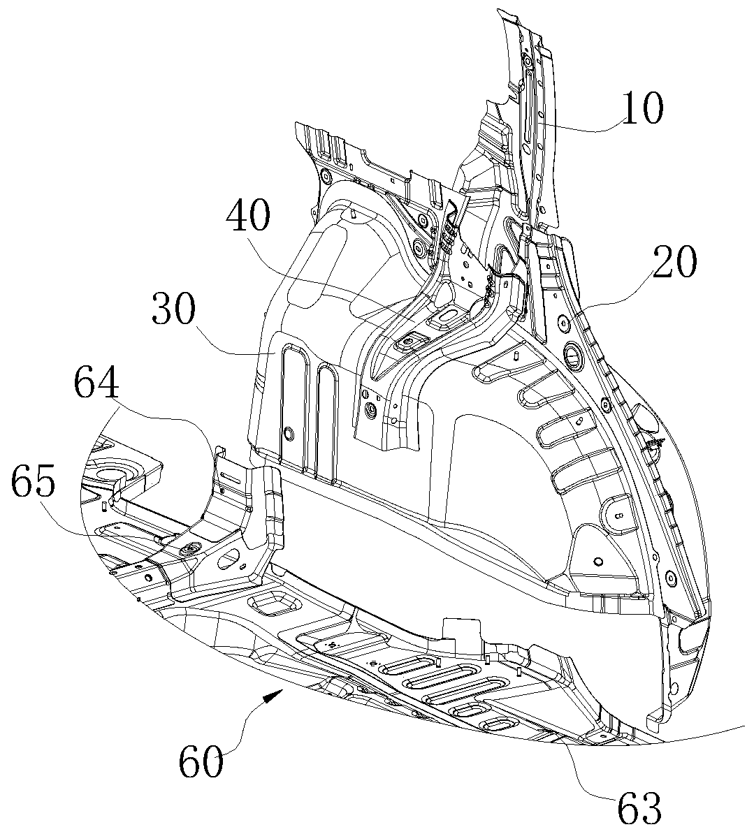
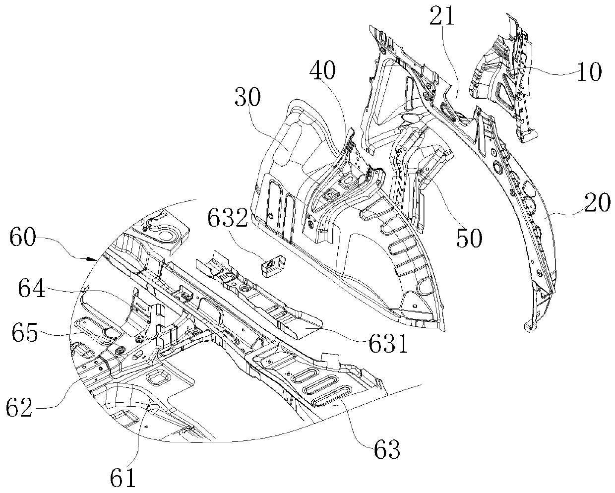
[0008] refer to Figure 1-Figure 3 , a C-pillar reinforcement plate connection structure, comprising a C-pillar reinforcement plate 10, the upper end of the C-pillar reinforcement plate 10 extends to the side beam of the vehicle body, the lower end is welded to the outer side of the rear wheel house outer panel 20, and the rear wheel house outer panel 20 is connected to the rear wheel house outer panel 20. Wheelhouse inner panel 30 is welded as a whole, and the inboard of rear wheelhouse inner panel 30 is provided with rear wheelhouse inner panel stiffener 40, and the upper end of rear wheelhouse inner panel stiffener 40 protrudes to the top of rear wheelhouse inner panel 30 and It is welded with the rear wheel house outer panel 20, and the described C-pillar reinforcing plate 10 and the rear wheel house inner panel reinforcing plate 40 are welded as one. The upper end of the C-pillar reinforcement plate 10 is connected to the side beam of the vehicle body, and the lower end i...


PUM


Abstract

The invention provides a C-column reinforcing plate connecting structure which is large enough in torsion rigidity and not likely to crack. The structure comprises a C-column reinforcing plate, the upper end of the C-column reinforcing plate extends to a boundary beam of a car body, the lower end of the C-column reinforcing plate is welded to the outer side of a back wheel cover outer plate, the back wheel cover outer plate and a back wheel cover inner plate are welded into a whole, a back wheel cover inner plate reinforcing plate is arranged at the inner side of the back wheel cover inner plate, the upper end of the back wheel cover inner plate reinforcing plate extends convexly to the upper portion of the back wheel cover inner plate to be welded to the back wheel cover outer plate, andthe C-column reinforcing plate and the back wheel cover inner plate reinforcing plate are welded into a whole. According to the scheme, the C-column reinforcing plate and the back wheel cover inner plate reinforcing plate are connected, a precise and effective force transfer path is formed between the C-column reinforcing plate and the back wheel cover inner plate, smooth stress transfer is ensured, local stress concentration is avoided, and energy is effectively absorbed. The whole transfer path forms a complete C ring, so that the torsional rigidity of the whole car body is improved, cracking of the car body is avoided, and jolting of the car body is lowered.

Description

technical field [0001] The invention relates to the field of auto parts, in particular to a connection structure of a C-pillar reinforcement plate. Background technique [0002] The C-pillar of the car is the third column that runs through the top cover and the lower body of the car's side wall. If the car's middle door is a revolving door, it plays an important role in carrying the middle door. At the same time, the torsional performance of the car's C-pillar on the body , the stiffness of the top cover, and the stiffness of the rear door lock pin installation point also play an important role, so a C-pillar reinforcement plate is usually installed on the C-pillar to improve the overall strength of the C-pillar. The connection structure of the C-pillar reinforcement plate is the key joint position of the body frame. Its structure directly affects the stiffness and mode of the frame body. Insufficient stiffness will easily lead to large local deformation of the body, stress ...

Claims


Application Information

Patent Timeline
IPC IPC(8): B62D25/04B62D25/16B62D25/20B62D27/02
CPCB62D25/04B62D25/163B62D25/2036B62D27/02
Inventor 徐文闫跃奇陈云李云明
Owner CHERY AUTOMOBILE CO LTD
Learn More