
Chamfering device of hardware die

A beveling and die technology, which is applied to positioning devices, driving devices, feeding devices, etc., can solve the problems of affecting the beveling efficiency, fast wear of the cutter head, and shortening the service life of the cutter head, so as to improve the bevel cutting efficiency and improve the use. Longevity, the effect of avoiding shaking

Inactive Publication Date: 2019-10-15
李义飞
View PDF10 Cites 2 Cited by
  • Summary
  • Abstract
  • Description
  • Claims
  • Application Information

AI Technical Summary

Problems solved by technology

[0003] The technical problem to be solved by the present invention is to provide a bevel cutting device for metal molds, so as to solve the problem that the bevel angle cannot be adjusted according to the actual situation in the prior art, which affects the bevel cutting efficiency, and the hardware mold cannot be lubricated during bevel cutting. The technical problem that causes the cutter head to wear out quickly and reduces the service life of the cutter head

Method used


Image

  • Chamfering device of hardware die
  • Chamfering device of hardware die
  • Chamfering device of hardware die

Examples


Embodiment Construction

[0027] In order to make the object, technical solution and advantages of the present invention clearer, the present invention will be further described in detail below in conjunction with the accompanying drawings and embodiments. It should be understood that the specific embodiments described here are only used to explain the present invention, not to limit the present invention.

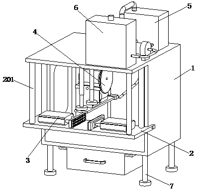
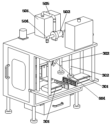
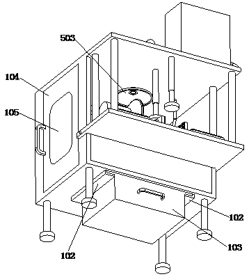
[0028] refer to Figure 1 to Figure 7It can be seen that the present invention provides a beveling device for metal molds, which includes a housing 1, a bearing plate 2, a limit assembly 3, a beveling assembly 4, a waste recycling assembly 5, a lubricating assembly 6 and four support legs 7. The housing 1 has a cavity structure, and the four supporting legs 7 are rectangularly distributed at the bottom of the housing 1, and the two ends of the bearing plate 2 are respectively screwed to the side walls of the housing 1, Four supporting columns 201 are distributed in a rectangular shape on the loadi...


PUM


Abstract

The invention discloses a chamfering device of a hardware die, and belongs to the technical field of hardware dies. The chamfering device comprises a shell, a bearing plate, a limiting component, a chamfering component, a waste recycling component, a lubricating component and four supporting legs, wherein the shell is of a cavity structure, the four supporting legs are distributed at the bottom end of the shell in a rectangular mode, the two ends of the bearing plate are in threaded connection with the side wall of the shell correspondingly, four supporting columns are distributed on the bearing plate in a rectangular manner, the top ends of the four supporting columns are fixedly connected with the top end of the shell, the limiting component is arranged on the bearing plate, the chamfering component is arranged in the shell, and the waste recycling component and the lubricating component are both arranged at the top end of the shell. According to the chamfering device, the chamfer angle can not be adjusted according to actual conditions, the chamfering efficiency is influenced, so that the abrasion of a cutter head is relatively high, and the service life of the cutter head is reduced.

Description

technical field [0001] The invention relates to the technical field of hardware molds, in particular to a bevel cutting device for hardware molds. Background technique [0002] Metal molds are used in industrial production with various presses and special tools installed on the presses to make metal materials into parts or products of the required shape through pressure. Such special tools are collectively referred to as hardware molds. All types of tools and products we all use in our daily production and lifestyle, ranging from the base from the machine device, the covering of the equipment equipment, to the small size of a screw, button and the shell of various household appliances, are all closely related to molds. During the production process of metal molds, bevel cutting is required. The existing bevel cutting device of the metal mold cannot adjust the bevel angle according to the actual situation, which affects the bevel cutting efficiency, and the metal mold cannot...

Claims


Application Information

Patent Timeline
Patent Type & Authority Applications(China)
IPC IPC(8): B23Q3/06B23Q11/10B23Q11/00B23Q5/28B23Q5/10
CPCB23Q3/06B23Q3/062B23Q5/10B23Q5/28B23Q11/00B23Q11/0046B23Q11/10Y02P70/10
Inventor 李义飞
Owner 李义飞
Learn More