Horizontal roof photovoltaic power station or heat collector mounting structure

A technology for installing structures and photovoltaic power stations, applied in the field of solar energy, can solve problems such as increasing construction costs, increasing heavy procedures, and damaging roofs

Pending Publication Date: 2019-10-11
WUHAN RIYI TECH CO LTD
View PDF0 Cites 0 Cited by
  • Summary
  • Abstract
  • Description
  • Claims
  • Application Information

AI Technical Summary

Problems solved by technology

The above methods either destroy the roof, or increase the construction cost and increase the heavy process

Method used


Image

  • Horizontal roof photovoltaic power station or heat collector mounting structure
  • Horizontal roof photovoltaic power station or heat collector mounting structure
  • Horizontal roof photovoltaic power station or heat collector mounting structure

Examples


Embodiment Construction

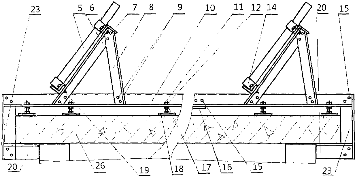
[0014] Photovoltaic panels (5) heat collectors are custom-made by professional enterprises according to given installation dimensions.

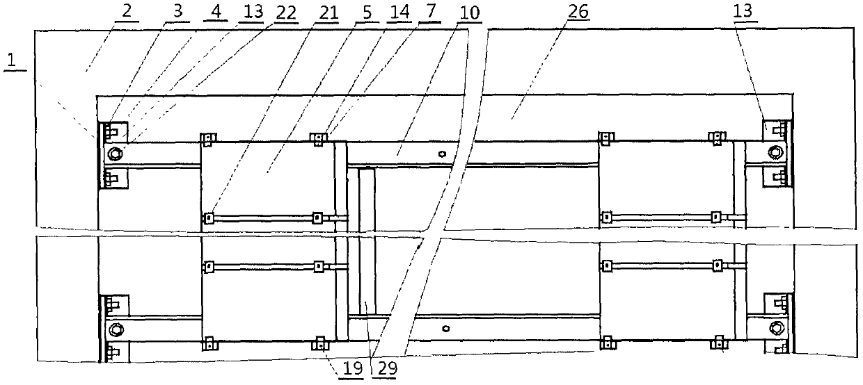
[0015] Steel structure parts such as bottom bracket (10), front support rod (6) and rear support rod (8), adjustment foot (18), lower cross bar (20), cross bar (7) are provided by a professional steel structure manufacturer Manufactured to order.

[0016] All bolts, nuts and washers are standard parts.

[0017] Transport all the above-mentioned components and other required devices, such as inverters, meters, wires, water pipes, etc. to the installation site, and install them step by step by professionals according to the design and installation drawings.


PUM


Abstract

The invention relates to a horizontal roof photovoltaic power station or a heat collector mounting structure in the field of solar energy. For a long time, people install solar photovoltaic modules orheat collectors on the roof of a horizontal building, which causes defects. In order to fix a photovoltaic module, a plurality of expansion bolt holes are drilled in a constructed roof during construction, so that the roof or a field cast-in-place cement platform is damaged, or a plurality of cement platforms are customized in a prefabricated part enterprise and moved to the roof, and then the photovoltaic power station or the heat collector is mounted on the cement platforms, so that the power station or the heat collector is prevented from being blown over by strong wind. In order to solvethe problems, the bottom bracket of the photovoltaic or heat collector is directly fixed on a parapet wall or is fixed on the edge of a roof through a hook-shaped component.

Description

technical field [0001] The invention relates to a horizontal roof photovoltaic power station or a heat collector installation structure in the field of solar energy. [0002] technical background [0003] For a long time, there have been disadvantages in installing solar photovoltaic modules or heat collectors on the roof of horizontal buildings. In order to fix the photovoltaic modules, many holes for expansion bolts must be drilled on the roof under construction, which will damage the roof or cast the concrete platform on site. , or customize many cement platforms in prefabricated parts companies, move them to the roof, and then install the above-mentioned photovoltaic power stations or collectors on the cement platforms, so as to prevent the power stations or collectors from being blown over by strong winds. Above-mentioned way either destroys roof, or increases construction cost and increases heavy operation. In order to solve the above-mentioned problems, a horizontal r...

Claims


Application Information

Patent Timeline
Patent Type & Authority Applications(China)
IPC IPC(8): H02S20/24F24S20/67F24S25/13
CPCH02S20/24Y02B10/10Y02B10/20Y02E10/50Y02P80/20
Inventor 邓传利
Owner WUHAN RIYI TECH CO LTD
Why Eureka
Try Eureka