
LED landscape buried light

A buried lamp and landscape technology, which is applied to lampshades, cooling/heating devices of lighting devices, lighting and heating equipment, etc., can solve the problems of poor heat dissipation, easy slipping, and general aesthetics of buried lamps, and achieve high brightness, Increase the anti-slip performance and increase the effect of bottom texture

Active Publication Date: 2019-10-11
广州市升和电子有限公司
View PDF8 Cites 6 Cited by
  • Summary
  • Abstract
  • Description
  • Claims
  • Application Information

AI Technical Summary

Problems solved by technology

At present, because the buried lamp is buried underground, the heat generated by the lamp body cannot enter the atmosphere due to the air tightness in the underground. Because the temperature of the entire buried lamp is very high, the heat dissipation of this type of buried lamp is generally poor.
[0003] In addition, the light-emitting surface of the upper end of the buried light is generally set to be flush with the ground. Since the light-emitting surface of the top of the buried light is generally a transparent tempered glass plate, the surface is smooth. Parks and other occasions, so it is easy to slip when tourists step on the upper end
Moreover, the light emitted by the buried lights is facing upwards, and the brightness is not high when viewed from a distance, and the position of the buried lights cannot even be found. Therefore, the decorative lighting effect is not good, and the aesthetics are relatively average.

Method used


Image

  • LED landscape buried light
  • LED landscape buried light

Examples


Embodiment Construction

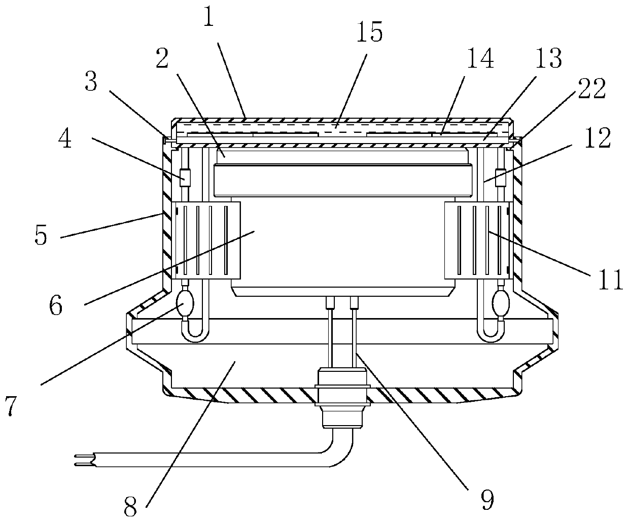
[0020] Such as figure 1 As shown, the LED landscape buried lamp includes a buried lamp housing 5, and the buried lamp housing 5 has a lamp body installation cavity 8 inside, and a lamp body 6 is installed in the lamp body installation cavity 8, and the lamp holder 2 of the lamp body 6 Facing the top opening end of the lamp body installation cavity 8, a light emitting panel 1 is installed on the top opening end of the lamp body installation cavity 8;

[0021] There is a sealed medium cavity 15 inside the light output panel 1. A light guide plate 13 is fixedly installed on the bottom surface of the medium cavity 15. A part of the light output panel 1 is installed in the lamp body installation cavity 8 and the top protrudes from the top of the buried lamp housing 5. The outer end of the body 6 is fixedly installed with more than one radiator 11, the lamp body 2 is fixedly installed on the inner wall of the lamp body installation cavity 8 through more than one radiator 11, and eac...


PUM


Abstract

The invention discloses an LED landscape buried lamp. the LED landscape buried lamp includes a buried lamp shell, the buried lamp shell is internally provided with a lamp body installation cavity, a lamp body is installed in the lamp body installation cavity, a lamp holder of the lamp body is directly opposite the opening end of the top face of the lamp body installation cavity, a light emitting panel is installed at the top opening end of the lamp body installation cavity, the light emitting panel is internally provided with a sealed medium cavity, a light guide plate is fixedly installed onthe bottom face of the medium cavity, the light emitting panel part is installed in the lamp body installation cavity and the top of the light emitting panel part protrudes from the top of the buriedlamp shell, more than one radiators are fixedly installed at the outer side ends of the lamp body, and the lamp body is fixedly installed on the inner wall face of the lamp body installation cavity through the more than one radiators. The LED landscape buried lamp can improve diversity of the irradiation angle of buried lamp light and can greatly improve the anti-slip performance at the same time,external force is used for allowing internal heat transfer, anti-slip and heat dissipation are integrated into one, the overall structure is simplified, design is more reasonable, and the appearanceis more artistic.

Description

technical field [0001] The invention relates to a buried lamp, in particular to an LED landscape buried lamp. Background technique [0002] Buried lights are widely used in the field of scientific and technological lighting in our country. Because they are buried in the ground for people to illuminate, they are named buried lights. At present, because the buried lamp is buried underground, the heat generated by the lamp body cannot enter the atmosphere due to the airtightness in the underground. Because the temperature of the entire buried lamp is very high, the heat dissipation of this type of buried lamp is generally poor. [0003] In addition, the light-emitting surface of the upper end of the buried light is generally set to be flush with the ground. Since the light-emitting surface of the top of the buried light is generally a transparent tempered glass plate, the surface is smooth. In places such as parks, it is extremely easy to slip when tourists step on the upper e...

Claims


Application Information

Patent Timeline
IPC IPC(8): F21S8/02F21V3/06F21V5/00F21V29/58F21Y115/10
CPCF21S8/022F21V3/06F21V5/00F21V29/59F21Y2115/10
Inventor 付秀华
Owner 广州市升和电子有限公司
Learn More