Water turbine capable of automatically removing waste and preventing blockage

A water turbine and garbage technology, applied in the direction of engine components, machines/engines, hydropower generation, etc., can solve the problems of economic loss, unable to drive the generator set to generate electricity, and the water turbine cannot operate normally, and achieve the effect of improving work safety.

Inactive Publication Date: 2019-10-11
朱雪英
View PDF6 Cites 0 Cited by
  • Summary
  • Abstract
  • Description
  • Claims
  • Application Information

AI Technical Summary

Problems solved by technology

[0003] At present, in most of the existing technologies, since the turbine operates in the water for a long time, some garbage, such as plastic shells, plastic bags, food packaging boxes, etc. Enter the inside of the draft tube, the surroundings of the draft tube are closed, and the garbage cannot come out, so it enters the volute of the turbine through the draft tube, and may get stuck between the blades of the runner, which will affect the normal operation of some components inside the volute , which in turn affects the normal rotation of the runner. If the runner is stuck and cannot rotate normally, the water energy cannot be converted into rotating mechanical energy, so that the generator set cannot be driven to generate electricity, which affects the normal power generation of the dam and causes economic damage. benefit loss
[0004] In order to solve the above problems, the inventor proposed a water turbine that can automatically remove garbage to prevent blockage, which has the advantage of automatically removing garbage entering the draft tube, ensuring the continuous entry of water flow, making the runner inside the volute continue to rotate, avoiding The inflow of garbage causes the runner to get stuck, causing the water turbine to fail to operate normally and affecting power generation

Method used


Image

  • Water turbine capable of automatically removing waste and preventing blockage
  • Water turbine capable of automatically removing waste and preventing blockage
  • Water turbine capable of automatically removing waste and preventing blockage

Examples


Embodiment Construction

[0019] The following will clearly and completely describe the technical solutions in the embodiments of the present invention with reference to the accompanying drawings in the embodiments of the present invention. Obviously, the described embodiments are only some, not all, embodiments of the present invention. Based on the embodiments of the present invention, all other embodiments obtained by persons of ordinary skill in the art without making creative efforts belong to the protection scope of the present invention.

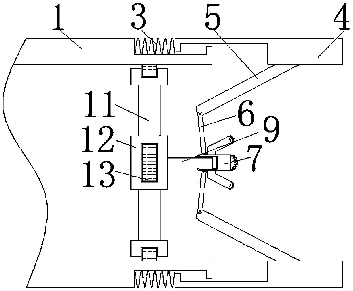
[0020] see Figure 1-4 , a water turbine capable of automatically removing garbage to prevent clogging, comprising: a draft tube 1 .

[0021] Such as figure 1 Shown: the rear end of draft tube 1 is fixedly installed with volute 2.

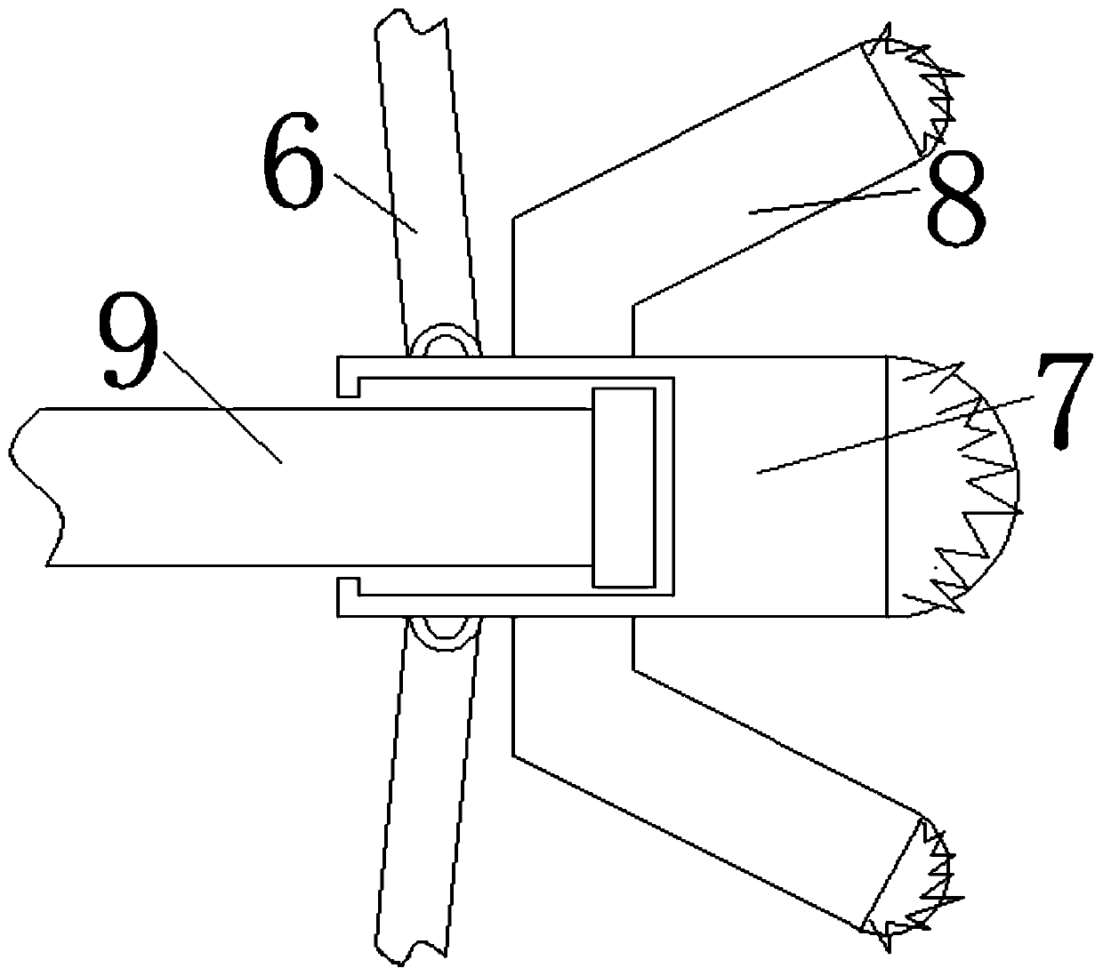
[0022] Such as figure 2 As shown: the front end of the draft tube 1 is elastically connected to the sliding tube 4 through the pressure spring 3, and the lower end of the sliding tube 4 is fixedly installed with two symmetrical...


PUM


Abstract

A water turbine capable of automatically removing waste and preventing blockage comprises a draft tube. A volute is fixedly installed at the back end of the draft tube. The front end of the draft tubeis elastically connected with sliding pipes through pressure springs. The lower ends in the sliding pipes are fixedly provided with two symmetrical connection rods. The left end of each connection rod is hinged to a hinged rod. The ends, far away from the connection rods, of the hinged rods are hinged to a moving column. The upper surface and the lower surface of the moving columns are both fixedly provided with stop columns. A fixing rod is installed in the left end of the moving column in a sliding manner. By means of cooperative use of the pressure springs, the sliding pipes, the connection rods, the hinged rods, the moving column and the stop columns, waste can be effectively removed, and therefore the water turbine has the advantage of being capable of automatically removing the waste entering the draft tube, continuous inflow of water is guaranteed, a runner in the volute can continuously rotate, and the situations that due to inflow of the waste, the runner gets stuck, the water turbine cannot normally operate, and power generation is influenced are avoided.

Description

technical field [0001] The invention relates to the technical field of power systems, in particular to a water turbine that can automatically remove garbage and prevent blockage. Background technique [0002] In power system technology, hydropower generation is also a commonly used power generation technology. Dams are often built to use water flow velocity or water level difference to generate power. Among them, hydraulic turbines are one of the discovery equipment that must be used in hydropower generation. It is a kind of machinery that transforms into rotating mechanical energy, thereby driving the generator to generate electric energy. The water turbine is roughly composed of: draft tube, volute and runner inside the volute. Its working principle is: water energy→rotating mechanical energy→driving the generator set generate electricity. [0003] At present, in most of the existing technologies, since the turbine operates in the water for a long time, some garbage, such...

Claims


Application Information

Patent Timeline
Patent Type & Authority Applications(China)
IPC IPC(8): F03B11/08
CPCF03B11/08Y02E10/20
Inventor 朱雪英
Owner 朱雪英
Why Eureka
Try Eureka