
Method of Excavating Diaphragm Wall into Groove

A technology of underground continuous wall and groove formation, which is applied in sheet pile wall, construction, infrastructure engineering and other directions, and can solve problems such as manual construction.

Active Publication Date: 2021-04-20
CHINA ROAD & BRIDGE
View PDF5 Cites 0 Cited by
  • Summary
  • Abstract
  • Description
  • Claims
  • Application Information

AI Technical Summary

Problems solved by technology

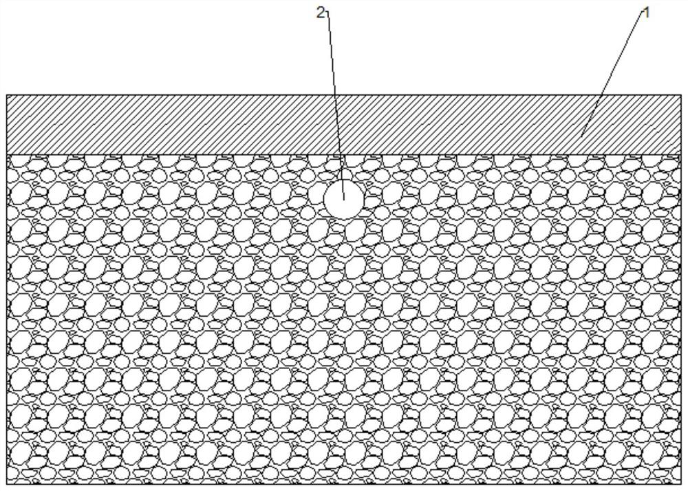
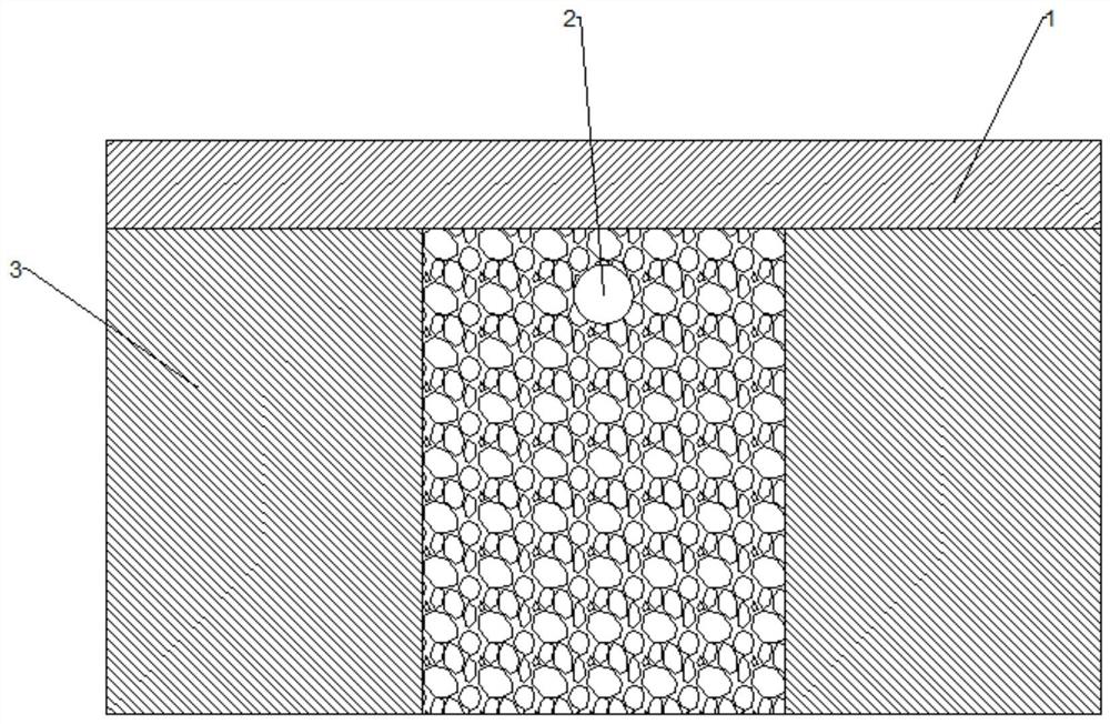
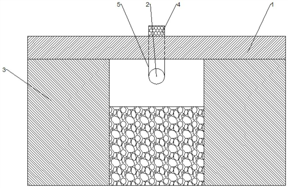
[0005] Still another object of the present invention is to provide a method for excavating underground diaphragm walls to form grooves, which can not only relocate underground pipelines, but also overcome the shortcomings of manual construction in the reverse method

Method used


Image

  • Method of Excavating Diaphragm Wall into Groove
  • Method of Excavating Diaphragm Wall into Groove
  • Method of Excavating Diaphragm Wall into Groove

Examples


Embodiment Construction

[0037] The present invention will be further described in detail below in conjunction with the accompanying drawings, so that those skilled in the art can implement it with reference to the description.

[0038] It should be noted that the experimental methods described in the following embodiments, unless otherwise specified, are conventional methods, and the reagents and materials, if not otherwise specified, can be obtained from commercial sources; in the description of the present invention, The terms "landscape", "portrait", "top", "bottom", "front", "rear", "left", "right", "vertical", "horizontal", "top", "bottom", The orientation or positional relationship indicated by "inner", "outer", etc. is based on the orientation or positional relationship shown in the drawings, which is only for the convenience of describing the present invention and simplifying the description, and does not indicate or imply that the referred device or element must have Certain orientations, co...


PUM


Abstract

The invention discloses a method for excavating an underground diaphragm wall to form a groove, which comprises the following steps: arranging suspension protection of the underground pipeline, excavating part of the soil under the underground pipeline, and then constructing a single-width underground continuous wall construction section through the underground pipeline. Rotary drilling holes; put half-width steel retaining walls in the construction section of the single-width diaphragm wall that goes down the underground pipeline, so that the two half-width steel retaining walls just enclose the construction section of the single-width diaphragm wall that goes down the underground pipeline; Step 6, use two The impact drilling rig pushes the half-width steel retaining wall into the ground; the hydraulic grab buckets are used to form grooves on both sides of the underground pipeline to the design depth, and then the high-pressure rotary jet machine is used to tilt down the soil under the underground pipeline to form holes; in the underground pipeline The hydraulic grab tank on one side is filled with clean water, so that the clean water is injected into the hydraulic grab tank on the other side of the underground pipeline from the rotary nozzle and gradually crushes the soil under the underground pipeline. The invention can not only make changes to the underground pipelines, but also overcome the shortcomings of manual construction in the reverse method.

Description

technical field [0001] The invention relates to the field of underground continuous wall construction. More specifically, the present invention relates to a method for excavating trenches in an underground continuous wall. Background technique [0002] The underground diaphragm wall is a kind of trenching machine used on the ground for basic engineering. Along the peripheral axis of the deep excavation project, a long and narrow deep trench is excavated under the condition of mud retaining wall. After the trench is cleaned, it is hung in the trench Reinforcement cages, and then use the conduit method to pour underwater concrete to form a unit trough section. In this way, a continuous reinforced concrete wall is built underground as a water interception, anti-seepage, load-bearing, and water-retaining structure. [0003] However, in the construction process of the underground diaphragm wall, it is often necessary to construct under the existing underground pipeline. Due to t...

Claims


Application Information

Patent Timeline
Patent Type & Authority Patents(China)
IPC IPC(8): E02D5/18
CPCE02D5/18
Inventor 贾其军郑甲佳
Owner CHINA ROAD & BRIDGE
Learn More