
Caput femoris prosthesis impactor extractor

A femoral head and prosthesis technology, applied in the direction of femoral head, prosthesis, medical science, etc., can solve the problems of high extraction efficiency, lower femoral head prosthesis, loose femoral stem prosthesis, etc., and achieve the effect of improving efficiency

Pending Publication Date: 2019-10-11
TIANJIN ZHENGTIAN MEDICAL INSTR CO LTD
View PDF0 Cites 2 Cited by
  • Summary
  • Abstract
  • Description
  • Claims
  • Application Information

AI Technical Summary

Problems solved by technology

[0005] Aiming at the problem in the prior art that the femoral stem prosthesis is loosened due to excessive and unstable force applied by the operator during hip arthroplasty, the purpose of the present invention is to provide a A femoral head prosthesis puller, the force required for the femoral head prosthesis puller to pull out the femoral head prosthesis is significantly reduced, and the force is evenly applied during the pull-out process, which has a greater impact on the stability of the femoral stem prosthesis Small and high extraction efficiency

Method used


Image

  • Caput femoris prosthesis impactor extractor
  • Caput femoris prosthesis impactor extractor
  • Caput femoris prosthesis impactor extractor

Examples


Embodiment 1

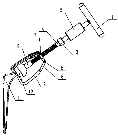
[0077] A femoral head prosthesis 10 beating device, comprising a force application unit, a force transmission unit and a fixing unit for fixing the femoral head prosthesis 10;

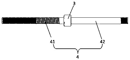
[0078] The force transmission unit is a dowel 4, and a limit block 3 is arranged on the dowel 4, and the limit block 3 divides the dowel 4 into two parts, the first part is a threaded rod 41, and the second part is a polished rod 42;

[0079] The force applying unit includes a first force applying member and a second force applying member; the first force applying member is a slider 2 sleeved on the polished rod 42, and the second force applying member is a handle 1 connected to the end of the polished rod 42 , the size of the handle 1 is greater than the size of the polished rod 42, the slider 2 is arranged between the handle 1 and the limit block 3, and can slide on the polished rod 42;

[0080] The fixing unit includes a receiving part 8 for accommodating the femoral head prosthesis 10 and a fixing...

Embodiment 2

[0085] A femoral head prosthesis 10 puller, except that the receiving part 8 is not provided with a connecting part 82, and the receiving cavity 84 is directly welded on one end of the threaded rod 41; The claw 9 is rotatably connected to the outside, and the rest of the structure is the same as that of the puller for the femoral head prosthesis 10 described in Embodiment 1.

Embodiment 3

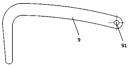
[0087] A femoral head prosthesis 10 puller, except that the number of connecting rods 6 is 6, the number of jaws 9 is 6, and the number of jaws 9 is "L", the rest of the structure is the same as that described in Example 1 The femoral head prosthesis 10 beater has the same structure.

[0088] The method for extracting the femoral head prosthesis 10 using the above-mentioned femoral head prosthesis 10 beating device may further comprise the steps:

[0089] (1) The operator holds the handle 1, places the accommodating cavity 84 on the outer surface of the femoral head prosthesis 10, grasps the claw 9 at the bottom of the femoral head prosthesis 10, and rotates the ferrule 7 until the claw 9 can be fixed on the The bottom of the femoral head prosthesis 10;

[0090] (2) The operator pulls the handle 1 forcefully, and hits the handle 1 with the slider 2 during the pulling process until the femoral head prosthesis 10 is pulled out.

[0091] Described femoral head prosthesis 10 bea...


PUM


Abstract

The invention provides a caput femoris prosthesis impactor extractor. The impactor extractor comprises a force application unit, a force transfer unit and a fixing unit for fixing a caput femoris prosthesis. The force application unit comprises a first force application piece and a second force application piece. The first force application piece is stressed and can impact the second force application piece, and the second force application piece is connected to one end of the force transfer unit; the fixing unit comprises a containing piece capable of containing the caput femoris prosthesis and a fixing piece for fixing the caput femoris prosthesis, and the containing piece and the fixing piece are both connected with the force transfer unit. According to the caput femoris prosthesis impactor extractor, stable and small force is applied to the caput femoris prosthesis in the perpendicular direction so that the caput femoris prosthesis can be disengaged from a femoral stem, and the influence caused by the caput femoris prosthesis on the femoral stem is greatly lowered; force generated when the first force application piece impacts the second force application piece can be convertedinto acting force for vibrating the caput femoris prosthesis, and the effect of loosening the caput femoris prosthesis is achieved, in addition, force stressed by the caput femoris prosthesis is uniform, and the caput femoris prosthesis extracting efficiency is greatly improved.

Description

technical field [0001] The invention belongs to the technical field of surgical instruments, and relates to a femoral head prosthesis puller. Background technique [0002] In the current field of medical technology, the number of patients undergoing artificial hip replacement in China is increasing day by day. Artificial hip replacement mainly uses surgical methods to remove the hip joint lesion and reconstruct the hip joint structure, so as to relieve or eliminate the pain and restore the joint. activities and original functions, and improve the quality of life of patients. [0003] The artificial hip joint prosthesis will wear to different degrees during daily life and work. At the same time, the wear of the femoral head prosthesis and the acetabular prosthesis is relatively common, resulting in inconvenience for the patient. At this time, hip revision surgery is required , to restore the activity of the artificial hip joint. During hip revision surgery, it was found tha...

Claims


Application Information

Patent Timeline
IPC IPC(8): A61F2/46A61F2/36
CPCA61F2/4607A61F2/3609A61F2002/3611A61F2/4603
Inventor 张长宁王经之鲍野
Owner TIANJIN ZHENGTIAN MEDICAL INSTR CO LTD
Learn More