Cardiac valve repair system

A technology for repairing a system and a heart valve, applied in the field of medical devices, can solve the problems of inability to visually observe the mitral valve clamp, low success rate, long operation time, etc., achieving the effect of easy operation, short time consumption, and avoiding cumbersome steps

Pending Publication Date: 2019-10-11
HANGZHOU VALGEN MEDTECH CO LTD
View PDF0 Cites 7 Cited by
  • Summary
  • Abstract
  • Description
  • Claims
  • Application Information

AI Technical Summary

Problems solved by technology

This interventional treatment method needs to be sent into the mitral valve clamp through a complicated and tortuous path in the patient's body, and it is impossible to visually observe whether the position of the mitral valve clamp in the patient's heart is reasonable, and the operator can only remotely operate the clamp outside the body. The cusp clamp clamps the valve leaflet and release process, so the operation time is longer and the success rate is lower

Method used


Image

  • Cardiac valve repair system
  • Cardiac valve repair system
  • Cardiac valve repair system

Examples


Embodiment 1

[0072] Such as Figure 3-Figure 33 As shown, a heart valve repair system includes at least two sutures 3000 with a certain axial length, a suture implantation device 1000 for implanting the sutures 3000 into different valve leaflets of the heart valve, and multiple A suture thread locking device 2000 for fixing together a suture thread 3000. The suture implantation device 1000 includes a pushing catheter 1210, a clamping assembly 1300 for clamping the valve leaflet, and a piercing assembly 1400 for piercing the valve leaflet. The clamping assembly 1300 and the piercing assembly 1400 are movably disposed in the pushing catheter 1210 . The suture 3000 is housed in the clamping assembly 1300 . The suture locking device 2000 includes a suture lock 2100 for fixing a plurality of sutures 3000, a lock pushing device 2200 detachably connected with the suture lock 2100, and a lock pusher 2200 for controlling the suture lock 2100 to fix Suture 3000 and release push control device 230...


PUM


Abstract

The invention discloses a cardiac valve repair system. The system comprises at least two suture lines, a suture line implanting device and a suture line knotting device, wherein the suture line implanting device is used for implanting the suture lines into different valve leaflets of a cardiac valve, and the suture line knotting device is used for fixing the suture lines together. The suture lineimplanting device comprises a pushing guide pipe, a clamping component used for clamping the valve leaflets and a puncturing component used for puncturing the valve leaflets. The suture line knottingdevice comprises a suture line lock catch used for fixing the suture lines, a lock catch pushing device detachably connected with the suture line lock catch, and a pushing control device used for controlling the suture line lock catch to fix and release the suture lines. According to the system, the suture lines are implanted into the anterior lobe and the posterior lobe of the bicuspid valve respectively, then the suture lines are fixed together, and the gap in the bicuspid valve is reduced or eliminated, so that the bicuspid valve is prevented from forming two holes, mitral regurgitation istreated, the operation process is simple, the operation cost is low, the trauma degree of a patient is low, the complication risk is low, and the recovery process is relatively quick.

Description

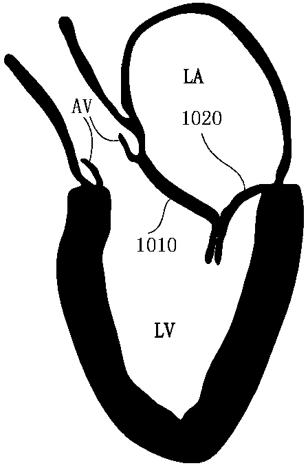
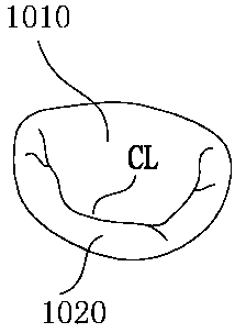
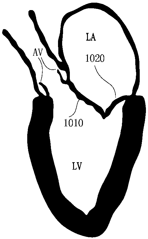
technical field [0001] The invention belongs to the technical field of medical devices and relates to a heart valve repair system. Background technique [0002] The mitral valve is a one-way "valve" between the left atrium (abbreviation: LA) and the left ventricle (abbreviation: LV), which can ensure blood flow from the left atrium to the left ventricle. The leaflets of the mitral valve are divided into anterior leaflet and posterior leaflet. When the left ventricle is in a diastolic state, the two are in an open state, and blood flows from the left atrium to the left ventricle; when the left ventricle is in a systolic state, the chordae are stretched to ensure The leaflets are not flushed to the atrial side by blood flow. Figure 1a-1b A normal, healthy mitral valve is shown, with the anterior and posterior leaflets closed well, allowing blood to flow from the left ventricle through the aortic valve (abbreviated: AV) to the aorta. Figure 2a-2b The mitral valve shown is di...

Claims


Application Information

Patent Timeline
IPC IPC(8): A61B17/00A61B17/06
CPCA61B17/00234A61B17/06A61B17/06004A61B2017/00243A61B17/00A61B17/04
Inventor 张庭超张伟伟孟旭潘湘斌郑贤章
Owner HANGZHOU VALGEN MEDTECH CO LTD
Why Eureka
Try Eureka