
Gas pulse pressure generator and pressure generating method based on impact switching

A technology of pulse pressure and gas pulse, which is applied in the direction of measuring fluid pressure, instruments, force/torque/power measuring instrument calibration/testing, etc. Can not be covered and other problems, to achieve the effect of easy operation and later maintenance, high waveform stability, simple and reliable structure

Active Publication Date: 2019-10-08
BEIJING CHANGCHENG INST OF METROLOGY & MEASUREMENT AVIATION IND CORP OF CHINA
View PDF8 Cites 9 Cited by
  • Summary
  • Abstract
  • Description
  • Claims
  • Application Information

AI Technical Summary

Problems solved by technology

[0003] In view of the deficiencies in the dynamic calibration of the existing pulse pressure: (1), the existing pulse pressure cannot cover the range of medium and low pressure 0.1MPa ~ 10MPa; (2), the existing hammer pulse pressure generator, the weight of the hammer body is relatively large , Piston cylinder sealing requirements and other factors are not easy to operate and maintain; (3), the existing pulse pressure generator method uses the drop hammer to generate, the pressure pulse width is difficult to control, the pressure amplitude repeatability is poor, and the hammer body and the piston are many The first collision caused problems such as pressure waveform oscillation

Method used


Image

  • Gas pulse pressure generator and pressure generating method based on impact switching
  • Gas pulse pressure generator and pressure generating method based on impact switching
  • Gas pulse pressure generator and pressure generating method based on impact switching

Examples


Embodiment 1

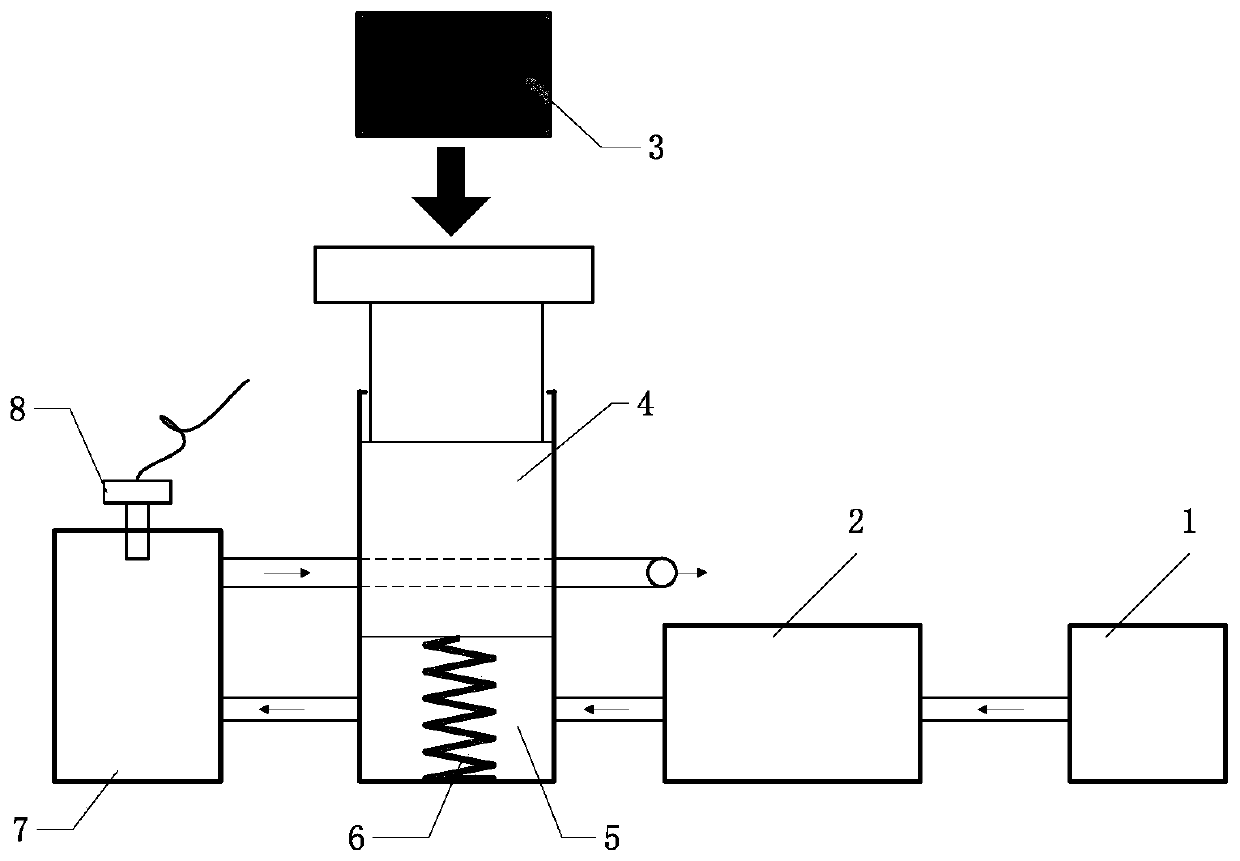
[0032] Such as figure 1 The gas pulse pressure generator based on impact switching disclosed in this embodiment is composed of a gas source 1, a gas pressure regulating mechanism 2, an excitation source 3, a piston rod 4, a piston cylinder 5, a spring 6, a pressure chamber 7 and a sensor 8 composition. One side of the piston cylinder 5 has an air inlet connected to the gas pressure regulating mechanism 2, and the other side has an air inlet at the middle part and an exhaust port at the bottom, and the air inlet in the middle part of the piston cylinder 5 is used to communicate with the gas pressure regulating mechanism 2. The exhaust port of the pressure chamber 7 is connected, and the exhaust port at the lower part of the piston cylinder 5 is used to communicate with the air inlet of the pressure chamber 7 . The piston rod 4 has a through hole. The gas source 1 communicates with the gas pressure stabilizing and regulating mechanism 2 . The gas pressure stabilizing and regu...


PUM


Abstract

The invention discloses a gas pulse pressure generator and a pressure generating method based on impact switching, and belongs to the technical field of measurement and testing. The gas pulse pressuregenerator based on impact switching disclosed by the invention comprises a gas source, a gas pressure-stabilizing and pressure-regulating mechanism, an excitation source, a piston rod, a piston cylinder, a spring, a pressure chamber and a sensor. The invention also discloses a pressure generating method based on impact switching. The position of the piston rod is adjusted by changing the excitation source to realize cooperative switching between through holes of the piston rod and the pressure chamber in order to adjust the pulse width of pulse pressure, so that high pulse width controllability and high waveform stability are achieved. The generated pulse pressure amplitude can be adjusted by adjusting the pressure-stabilizing and pressure-regulating mechanism, so that high amplitude repeatability is achieved. The gas pulse pressure generator has the advantages of simple and reliable structure, and convenience in operation and later maintenance. Through adoption of the gas pulse pressure generator and the pressure generating method, the pulse pressure waveform, the pulse width and the amplitude can be adjusted accurately in a controllable manner, so that the calibration demand ofa dynamic pressure sensor in test fields is met. The test fields include generator, cannonball and high-speed train test fields.

Description

technical field [0001] The invention belongs to the technical field of metering and testing, and relates to a gas pulse pressure generator based on impact switching and a pressure generating method. Background technique [0002] The pulse pressure generator is the main core equipment for dynamic calibration of pulse pressure. It provides a certain dynamic amplitude similar to half-sine pressure pulses that meet the pulse width requirements. The pulse pressure generated can calibrate the dynamic sensitivity of the dynamic pressure sensor / test system. The existing pulse pressure generators basically adopt the method of free-falling hammer to impact the hydraulic piston, which is mainly used for high-pressure and ultra-high-pressure dynamic calibration. Poor repeatability, multiple collisions between the hammer body and the piston cause pressure waveform oscillation and other problems. Contents of the invention [0003] In view of the deficiencies in the dynamic calibration ...

Claims


Application Information

Patent Timeline
Patent Type & Authority Applications(China)
IPC IPC(8): G01L25/00G01L27/00
CPCG01L25/00G01L27/005
Inventor 李博杨军王洪博尹肖
Owner BEIJING CHANGCHENG INST OF METROLOGY & MEASUREMENT AVIATION IND CORP OF CHINA
Learn More