Self-locking device of linear actuator and linear actuator

A technology of linear actuator and self-locking device, applied in transmission, clutch, one-way clutch, etc., can solve the problems of self-locking failure, accident, insufficient self-locking force, etc., and achieves small volume occupation and small installation space requirements , the effect of simple structure

Pending Publication Date: 2019-10-08
NINGBO HAISHIKAI DRIVER TECH CO LTD
View PDF9 Cites 1 Cited by
  • Summary
  • Abstract
  • Description
  • Claims
  • Application Information

AI Technical Summary

Problems solved by technology

At present, the self-locking function of this type of lifting column on the market is mostly realized by the brake torsion spring. When the transmission screw rotates in the opposite direction, the brake torsion spring is used to drive the brake torsion spring to hold tightly to generate braking force, which relies on the brake torsion spring. The self-locking ...

Method used


Image

  • Self-locking device of linear actuator and linear actuator
  • Self-locking device of linear actuator and linear actuator
  • Self-locking device of linear actuator and linear actuator

Examples


Embodiment 1

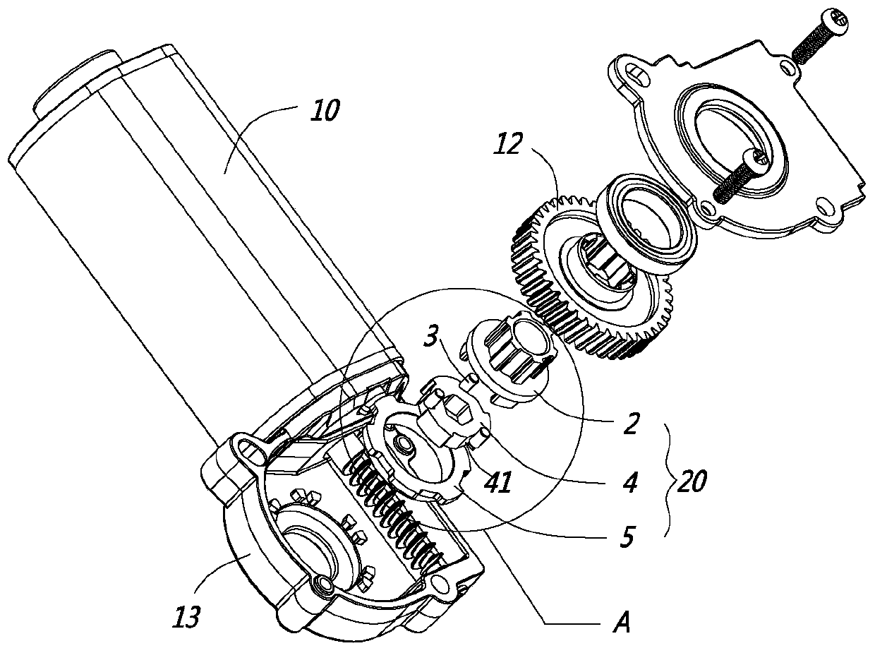
[0033] Such as Figure 1 to Figure 7 As shown, the specific preferred structure of Embodiment 1 of the self-locking device 20 of the present invention is shown.

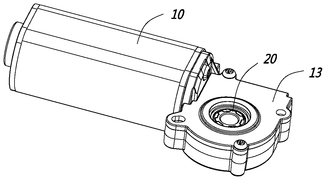
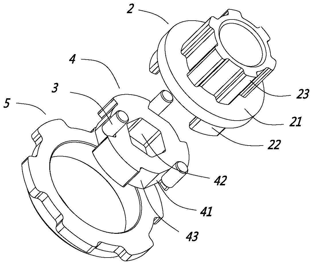
[0034] Such as figure 1 As shown, the self-locking device 20 of this embodiment is arranged between the driving motor 10 and the transmission screw of the linear actuator. The self-locking device 20 is connected with the driving motor 10 on the one hand, and is connected with the transmission screw on the other hand. In terms of, the self-locking device 20 of the present embodiment includes a track outer ring 5 and a rotating inner ring 4 rotatably arranged in the track outer ring 5, the outer side wall of the rotating inner ring 4 is provided with a ratchet groove 41, and the ratchet groove 41 is equipped with a ball 3, and a ball 3 is set in the ratchet groove 41. When the rotating inner ring 4 rotates in the forward direction, the rotating inner ring 4 can push and roll normally, and when the rotating inner ring ...

Embodiment 2

[0049] Such as Figure 8 As shown, this embodiment is a linear actuator. The linear actuator in this embodiment is a lifting column, which is mainly used on a lifting table, and mainly includes a driving motor 10, a driving screw, and a driving nut. The lifting column is a three-section column. The transmission screw includes a primary screw 61 and a secondary screw 62. The transmission nut also includes a primary nut 71 and a secondary nut 72. The specific structure and principle of this three-section lifting column are available in the existing There are a lot of disclosures in the technology, and this article will not elaborate too much. The improvement point of this embodiment is that the driving motor 10 of the lifting column is installed with a self-locking device 20 as in Embodiment 1 or the solution equivalent to it.

[0050] It should be noted that this embodiment only shows one of the lifting columns, and the linear actuator of the present invention is not limited to...


PUM


Abstract

The invention discloses a self-locking device of a linear actuator, and belongs to the field of the linear actuators. The self-locking device is arranged between a driving motor and a transmission screw rod of the linear actuator; the self-locking device comprises a rail outer ring and a rotating inner ring rotationally arranged in the rail outer ring, a ratchet wheel groove is formed in the outerside wall of the rotating inner ring, and a ball is contained in the ratchet wheel groove; the rotating inner ring is connected with a planetary shifting fork, and when the planetary shifting fork rotates positively in a forward direction, the planetary shifting fork abuts against the rotating inner ring to rotate in the forward direction; when the planetary shifting fork rotates positively in areverse direction, the planetary shifting fork abuts against the ball, and the ball abuts against the rotating inner ring to rotate in the reverse direction; and when the rotating inner ring rotates positively in the reverse direction, the ball is squeezed into the space between the ratchet wheel groove and the rail outer ring, and one-way self-locking is formed. The invention further discloses the linear actuator adopting the self-locking device, the self-locking device has the advantages that the self-locking force of the linear actuator is improved, and meanwhile, normal transmission movement is not influenced.

Description

【Technical field】 [0001] The invention relates to a self-locking device of a linear actuator and the linear actuator, belonging to the field of linear actuators. 【Background technique】 [0002] Linear actuators are currently widely used in various fields, including electric lift tables, electric beds, electric sofas, etc. The structure of this linear actuator usually includes a drive motor, a drive screw, and a drive nut. The drive motor drives the drive screw to rotate , when the transmission screw rotates, it drives the transmission nut to move axially, and the transmission nut can be connected to the driving object, so as to realize the driving purpose. [0003] Take the electric lift table as an example. At present, the electric lift table includes a lifting column. The lifting column includes a drive motor, a transmission screw, and a drive nut. The drive nut drives the pipe to rise or fall. This type of electric lift table needs a self-locking Functional, that is, whe...

Claims


Application Information

Patent Timeline
IPC IPC(8): F16H25/20F16H25/24F16D41/064
CPCF16H25/2015F16H25/2454F16D41/064F16D2041/0646
Inventor 何立东
Owner NINGBO HAISHIKAI DRIVER TECH CO LTD
Why Eureka
Try Eureka