
Variable-gauge steel wheel driving device

A driving device and variable rail technology, applied in the field of rail vehicles, can solve the problems of reducing operation efficiency, complicated operation process, increasing equipment cost, etc., and achieve the effect of simple structure

Pending Publication Date: 2019-10-08
BEIJING LEAD TIME SCI & TECH
View PDF0 Cites 2 Cited by
  • Summary
  • Abstract
  • Description
  • Claims
  • Application Information

AI Technical Summary

Problems solved by technology

[0003] The traditional way of changing the track needs to replace the axle or wheel, the operation process is complicated, time-consuming and labor-intensive; if several wheels and axles with different gauges are equipped on one equipment at the same time, the volume of the equipment will be increased, the passability will be deteriorated, and the equipment will be increased. cost, the increased load reduces operating efficiency and increases energy consumption

Method used


Image

  • Variable-gauge steel wheel driving device
  • Variable-gauge steel wheel driving device
  • Variable-gauge steel wheel driving device

Examples


Embodiment Construction

[0029] The core of the present invention is to provide a variable gauge steel wheel driving device, which can change the spacing of the driving wheels and match the tracks of different gauges.

[0030] In order to enable those skilled in the art to better understand the technical solutions of the present invention, the variable gauge steel wheel driving device of the present application will be described in detail below in conjunction with the accompanying drawings and specific implementation methods.

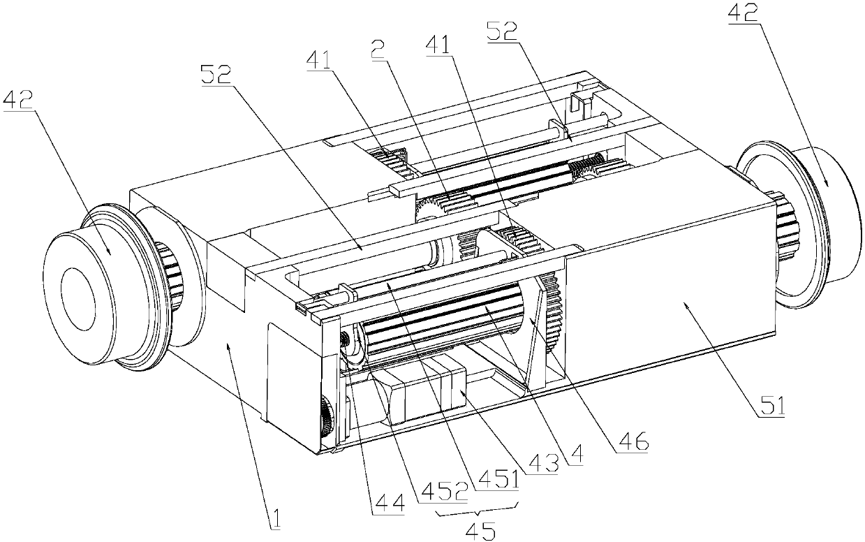
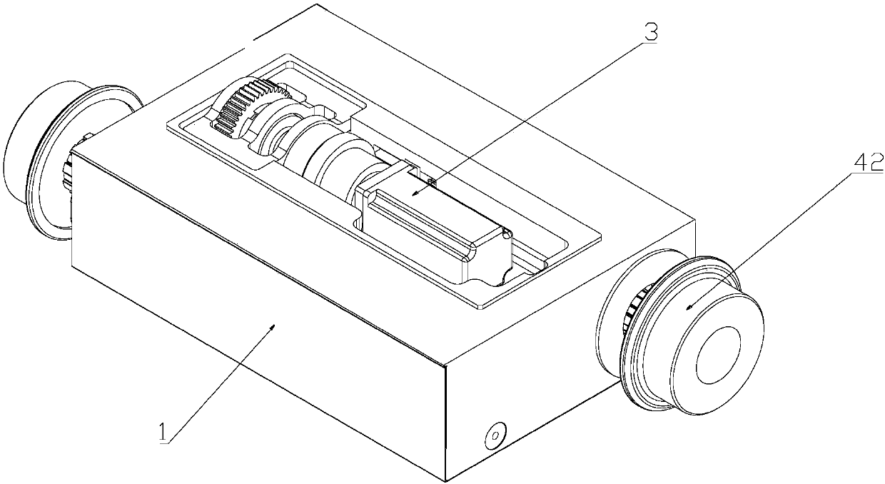
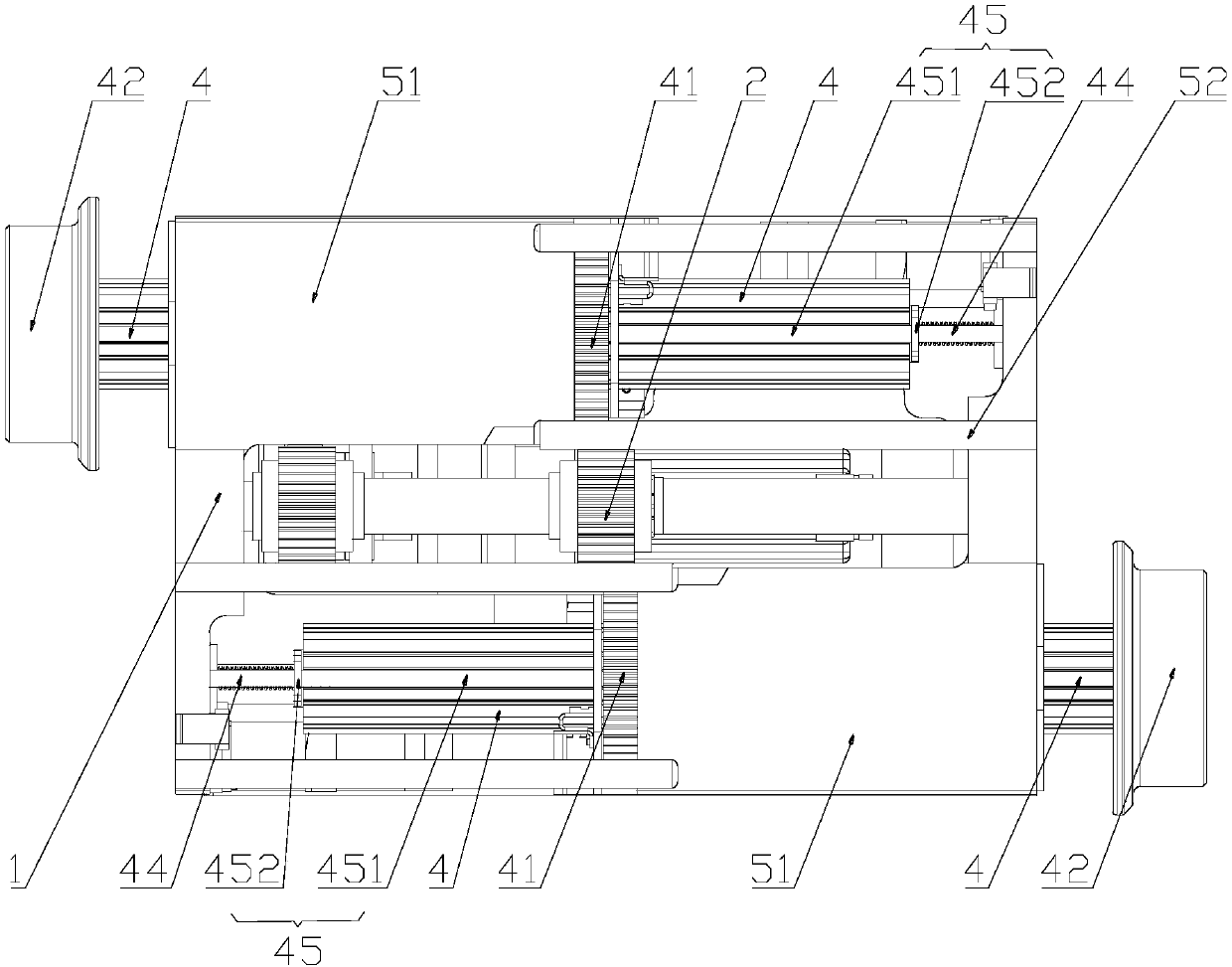
[0031] Such as Figure 1A and Figure 1B As shown, are the axonometric structural diagrams of two different angles of the variable gauge steel wheel driving device provided by the present invention respectively, Figure 1A For the oblique upward perspective, Figure 1B It is a view from the bottom; the variable gauge steel wheel driving device provided by the present invention includes structures such as a frame 1, a driving wheel 2, and a telescopic shaft 4. The frame 1 is a r...


PUM


Abstract

The invention discloses a variable-gauge steel wheel driving device. A drive wheel is rotationally arranged on a machine frame and is driven by a walk driving device to operate. Two telescopic shaftsare in center symmetry about the drive wheel. The two sides of the drive wheel are each provided with a driven wheel. The drive wheel can drive the two driven wheels and the telescopic shafts to rotate at the same time. The extending-out end of each telescopic shaft is provided with a walking wheel. The machine frame is provided with extending and retracting drivers. The extending and retracting drives can drive lead screws to rotate. The lead screws are sleeved with limiters in a screw-thread fit manner. The limiters keep synchronous horizontal movement with the telescopic shafts, and the limiters and the telescopic shafts can relatively rotate. The limiters do not influence rotation of the telescopic shafts and only control axial displacement of the telescopic shafts. When the interval between the two walking wheels need to be adjusted, the extending and retracting drivers drive the lead screws to enable the telescopic shafts to extend out outwards or retract inwards in the axial direction, so that the purpose of changing the interval between the walking wheels is achieved, and the variable-gauge steel wheel driving device can be rapidly adapted to rails of different widths; andthe variable-gauge steel wheel driving device is simple in structure and does not occupy too much space.

Description

technical field [0001] The invention relates to the technical field of rail vehicles, and further relates to a variable gauge steel wheel driving device. Background technique [0002] At present, the domestic train track adopts a standard gauge of 1435mm, but in some cases, it is necessary to use tracks of different sizes, such as maintenance trenches, mining machinery, port machinery, etc. When changing between two different gauge tracks, two sets of different gauges are usually used Steel wheels with different distances are used for track changing operations. [0003] The traditional way of changing the track needs to replace the axle or wheel, the operation process is complicated, time-consuming and laborious; if several wheels and axles with different gauges are equipped on one equipment at the same time, the volume of the equipment will be increased, the passability will be deteriorated, and the equipment will be increased. Increased load reduces operating efficiency a...

Claims


Application Information

Patent Timeline
IPC IPC(8): F16H1/22B61C9/48
CPCF16H1/22B61C9/48
Inventor 张渝高晓蓉王黎王泽勇赵全轲章祥黄炜王小伟赵波张立玮许安东
Owner BEIJING LEAD TIME SCI & TECH
Learn More