Attitude adjustment method and hydraulic system for antenna testing
A technology of hydraulic system and adjustment method, which is applied in the directions of antenna, antenna radiation pattern, and antenna components, etc., can solve the problems of time-consuming antenna adjustment, poor adjustment accuracy, and high labor cost consumption.
- Summary
- Abstract
- Description
- Claims
- Application Information
AI Technical Summary
Problems solved by technology
Method used
Image

Examples
Embodiment 1
[0067] An attitude adjustment hydraulic system for antenna testing, including a platform hydraulic subsystem, a slewing platform, an erecting hydraulic subsystem, a level, a controller, and a range finder;
[0068] The slewing platform is installed on the platform hydraulic subsystem, the erecting hydraulic subsystem is installed on the slewing platform for erecting or recovering the antenna under test, and the slewing platform is used to drive the erecting hydraulic The subsystem and the antenna under test rotate in the horizontal direction; the level is used to monitor the hydraulic subsystem of the platform, and the monitoring result is sent to the controller; the controller can receive the monitoring result that the level is used for monitoring , and be able to control the platform hydraulic subsystem and the erecting hydraulic subsystem;
[0069] The rangefinder is used to measure the distance between the antenna under test and the external test reference surface, and sen...
Embodiment 2
[0083] A method for attitude adjustment for antenna testing, using the above-mentioned attitude adjustment hydraulic system for antenna testing, comprising the following steps:
[0084] S1. The controller controls the platform hydraulic subsystem to raise the test platform of the platform hydraulic subsystem until the angles between the length and width directions of the test platform and the horizontal plane are less than or equal to ±1′;
[0085] S2. The controller controls the erecting hydraulic subsystem to erect the antenna under test until the erecting cylinder of the erecting hydraulic subsystem reaches the limit position;
[0086] S3. Using a rangefinder to measure the distance between the antenna under test and the test reference surface, and adjust the slewing platform and the legs of the hydraulic subsystem of the platform according to the measurement result of the distance, so that the antenna under test is parallel to the test reference surface.
[0087] In S1, th...
Embodiment 3
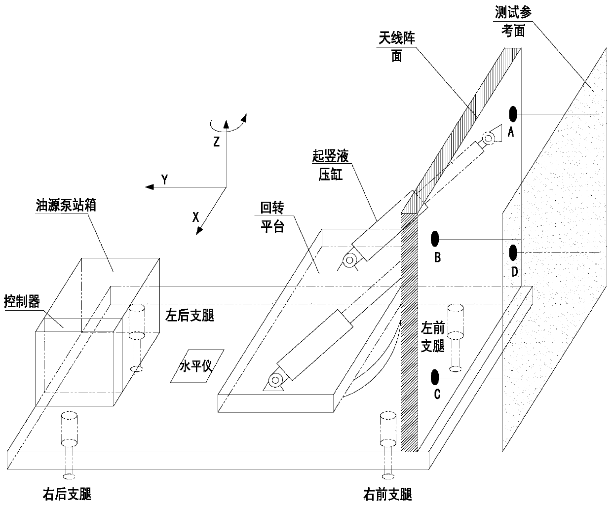
[0114] An attitude adjustment hydraulic system for antenna testing, such as figure 2 , is a schematic diagram of the antenna after adjusting its attitude. During the antenna test, the measured array should be parallel to the reference plane (the array is perpendicular to the ground), and the actual detection method is (A, B, C, D) max-(A, B, C, D) min≤1mm (any point ), and |ZB-ZA|≤1 (ZB: the coordinates of point B in the Z direction, ZA: the coordinates of point A in the Z direction,) (that is, the height difference between the two points AB and the ground), through the reference plane The laser rangefinder measures the relative positions of the four points.
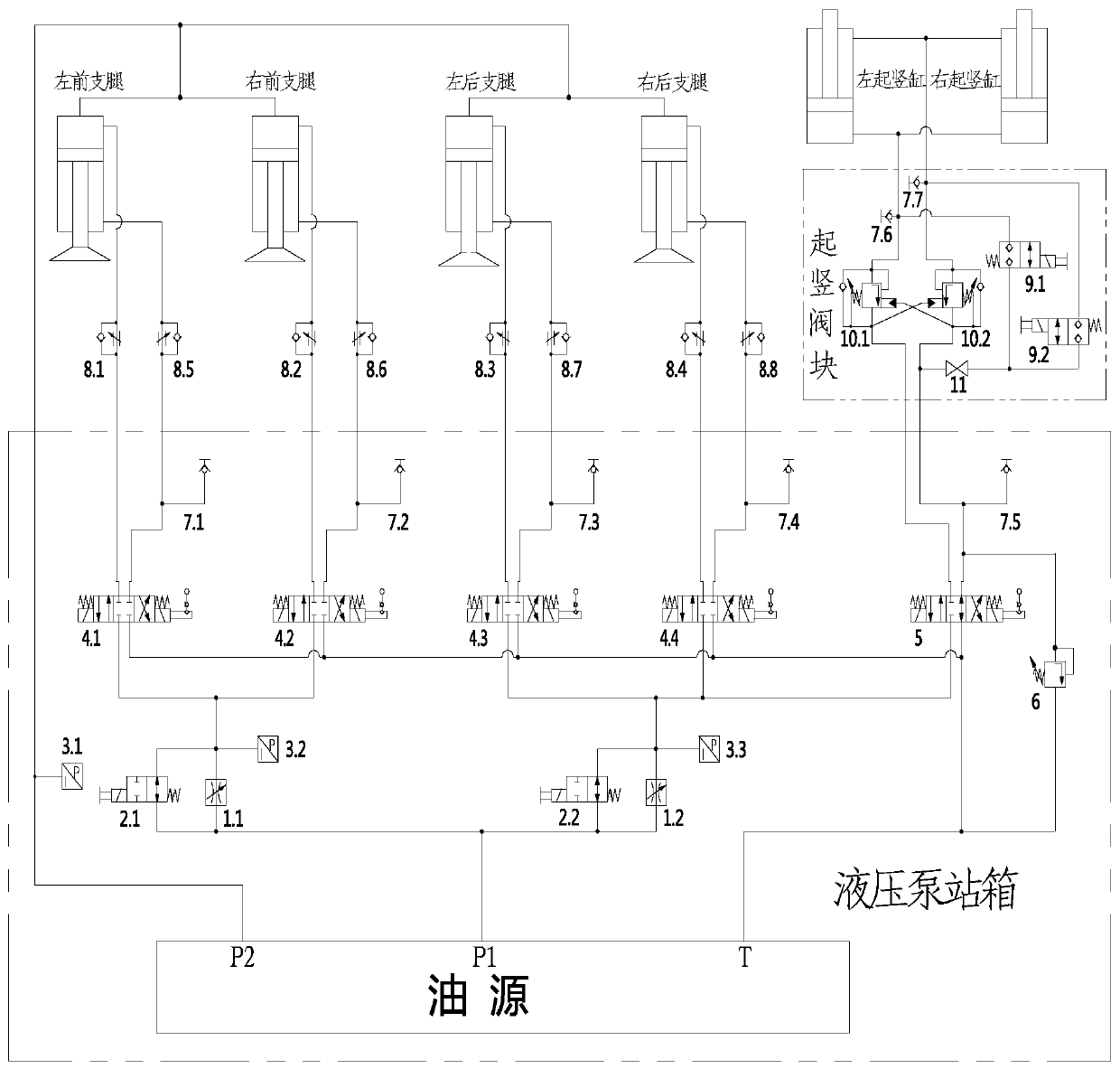
[0115] In order to ensure that the final attitude of the antenna meets the above requirements, the designed hydraulic system can realize the following functions: In order to ensure the stability of the antenna during erection, it is necessary to use the left front outrigger, right front outrigger, left rear outrigger, ...
PUM
 Abstract
Description
Claims
Application Information
 - R&D
- Intellectual Property
- Life Sciences
- Materials
- Tech Scout
- Unparalleled Data Quality
- Higher Quality Content
- 60% Fewer Hallucinations
Browse by: Latest US Patents, China's latest patents, Technical Efficacy Thesaurus, Application Domain, Technology Topic, Popular Technical Reports.
© 2025 PatSnap. All rights reserved.Legal|Privacy policy|Modern Slavery Act Transparency Statement|Sitemap|About US| Contact US: help@patsnap.com