
A method for reducing propeller hydrodynamic noise by introducing jet flow in front of the propeller

A propeller and hydrodynamic technology, applied in the direction of rotating propellers, rotary propellers, instruments, etc., to reduce the hydrodynamic noise of the propeller, reduce the unevenness of the stern wake, and improve the anti-cavitation performance

Active Publication Date: 2021-05-28
NAVAL UNIV OF ENG PLA
View PDF7 Cites 0 Cited by
  • Summary
  • Abstract
  • Description
  • Claims
  • Application Information

AI Technical Summary

Problems solved by technology

[0009] Aiming at the limitations of two typical technical measures currently available for naval propeller hydrodynamic noise control, the present invention provides a new method for reducing propeller hydrodynamic noise by introducing jet flow in front of the propeller, which not only improves the unevenness of accompanying flow better, but also has no additional Acoustic side effects, and easy to implement, can effectively improve the anti-cavitation performance of the propeller and reduce the hydrodynamic noise of the propeller under the condition that the hull empennage configuration-7-blade configuration and the blade shape remain unchanged

Method used


Image

  • A method for reducing propeller hydrodynamic noise by introducing jet flow in front of the propeller
  • A method for reducing propeller hydrodynamic noise by introducing jet flow in front of the propeller
  • A method for reducing propeller hydrodynamic noise by introducing jet flow in front of the propeller

Examples


Embodiment Construction

[0026] pass below Figure 1 to Figure 5 And the way of enumerating some optional embodiments of the present invention, the technical solution of the present invention (including the preferred technical solution) is described in further detail, and any technical feature and any technical solution in this embodiment do not limit the protection scope of the present invention .

[0027] The implementation process of the jet flow before the propeller designed in the present invention is introduced to reduce the propeller hydrodynamic noise method is as follows Figure 4 as shown,

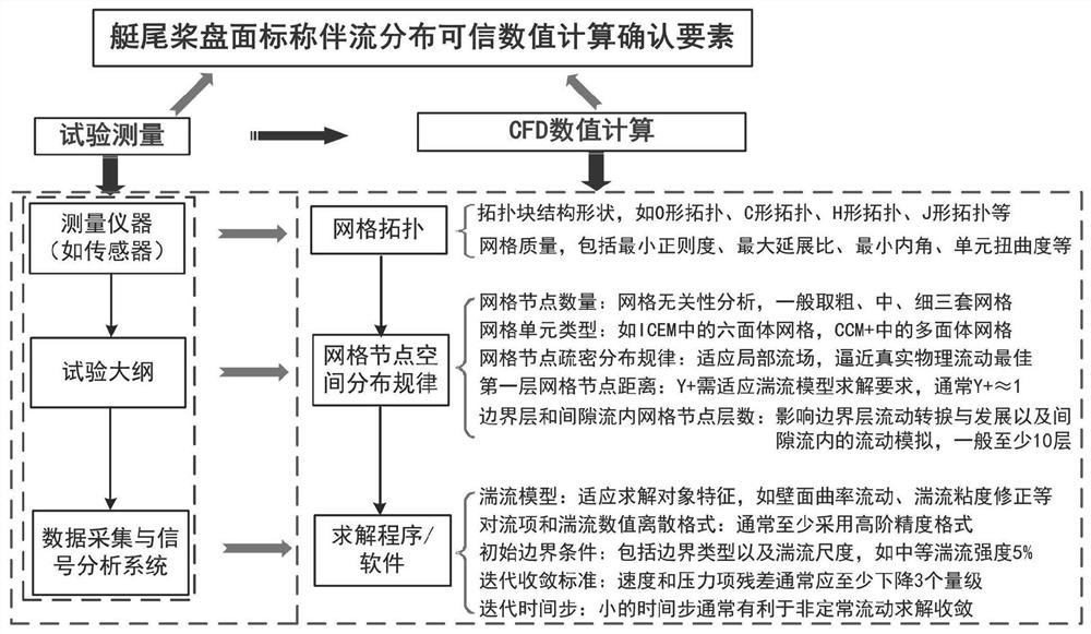
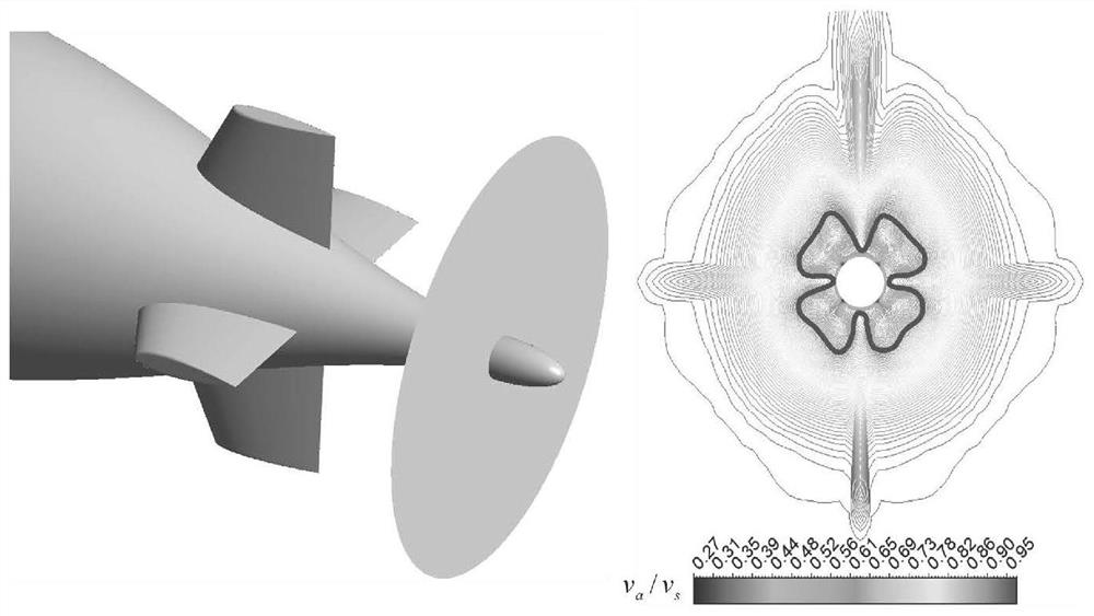
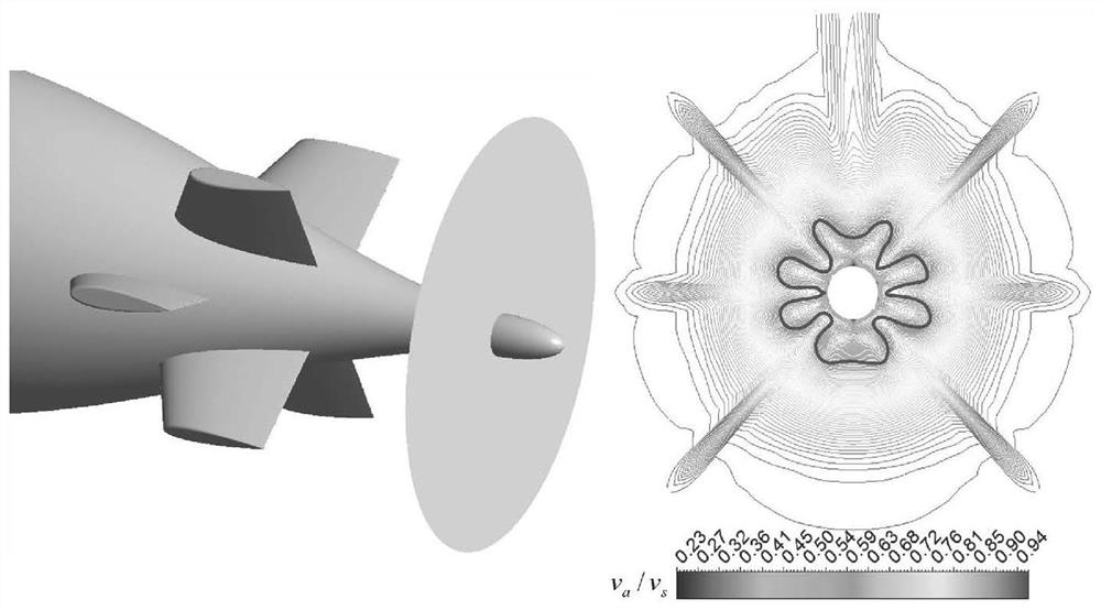
[0028] Step S1, using experimental measurement or CFD numerical calculation method to obtain the nominal wake distribution at the stern rotor disk;

[0029] During the test measurement, it is completed for the model-scale or large-scale fully-attached hull; during the CFD numerical calculation, the analysis object can be the model-scale, large-scale or real-scale fully-appended hull.

[0030] During C...


PUM


Abstract

The invention discloses a method for reducing propeller hydrodynamic noise by introducing jet flow in front of the propeller. After obtaining the nominal wake distribution of the stern rotor disk surface, the distribution curves of the axial velocity component along the circumferential direction at different radii are extracted, and the circumferential angular position of the pulsation trough of the axial velocity component and the velocity value of each pulsation trough at 0.4R are read. Calculate the circumferential average value of the axial velocity component at different radii within the set range, determine the circumferential angular position and diameter of the reference nozzle hole along the hull empennage, finally determine the radial position and diameter of the serial diameter nozzle holes, and determine the propeller Front jet introduction technology solution. After the jet is introduced, the pulsation trough of the axial velocity component with a given radius is eliminated, the velocity gradient in the radial range is suppressed, and the unevenness of wake flow is reduced. The invention can improve the anti-cavitation performance of the 7-blade propeller and reduce the hydrodynamic noise target under the condition that the hull empennage configuration-7-blade configuration and the blade shape remain unchanged, and there is no additional stator-rotor blade interaction line spectrum The noise source is introduced, and it is easy to modify and implement.

Description

technical field [0001] The invention belongs to the technical field of ship propellers, and in particular relates to a method for actively or passively introducing a jet flow upstream of a propeller into a propeller disc surface to reduce propeller hydrodynamic noise, which can be used for submarine propellers, pump jet propellers and surface ship propellers. Background technique [0002] The cavitation tube test results of the propeller noise in the stern wake field show that ([1] Seol H, CheolsooP. th International Congress on Acoustics, Madrid, 2007): Propeller has no cavitation noise and cavitation noise, both of which are dominated by discrete line spectrum noise at its blade frequency and its harmonic frequency. Suppressing line spectrum noise is the key to controlling propeller hydrodynamic noise. [0003] It is stated in the classic monograph on acoustic theory ([2] Ross. Mechanics of Underwater Noise (underwater noise principle). New York: Pergamon Press, 1976): th...

Claims


Application Information

Patent Timeline
Patent Type & Authority Patents(China)
IPC IPC(8): B63H1/28G06F30/23G06F30/28G06F30/15G06F119/10G06F113/08G06F119/14
CPCB63H1/28G06F2119/10G06F30/23Y02T90/00
Inventor 杨琼方王永生邹义张志宏吴杰长曾凡明王悦民
Owner NAVAL UNIV OF ENG PLA
Learn More