Device assembled with transmission shaft with self-destruct function

A transmission shaft and function technology, which is applied in the field of assembling a transmission shaft with a self-destruct function, can solve problems such as the service life of the transmission shaft cannot reach the predetermined time, the transmission shaft is strained, and the transmission shaft is broken, so as to achieve positioning reliability The effect of no movement, avoiding strain, and convenient flat groove width

Active Publication Date: 2019-10-08
GUIZHOU HONGLIN MACHINERY
View PDF6 Cites 0 Cited by
  • Summary
  • Abstract
  • Description
  • Claims
  • Application Information

AI Technical Summary

Problems solved by technology

However, when carrying out the assembly of this type of propeller shaft at present, it is as follows Figure 4 After the outer circle ФS shown is clamped by the clamping tool, it is placed upwards on the workbench, and then several precision mechanical parts are assembled on the outer circle under the thread MA, and then several Precision mechanical parts are fixedly installed on the transmission shaft. During the process of tightening the nut, the weak part of the transmission shaft with self-destruct function will be subject to a certain amount of torque and tension. These torque and tension are due to the strength of the assembler. distinct difference
Due to the current clamping method, the weak part of the transmission shaft can be stressed, so that the transmission shaft will be strained, twisted, cracked during assembly, or when working on the tester, or the user uses a section After a period of time, the transmission shaft breaks, so that the service life of the transmission shaft cannot reach the predetermined time

Method used


Image

  • Device assembled with transmission shaft with self-destruct function
  • Device assembled with transmission shaft with self-destruct function
  • Device assembled with transmission shaft with self-destruct function

Examples


Embodiment Construction

[0024] The present invention will be further described below in conjunction with the accompanying drawings and embodiments, but not as a basis for limiting the present invention.

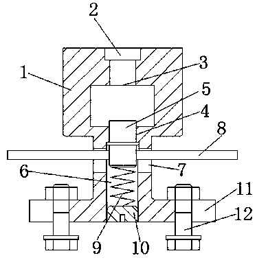
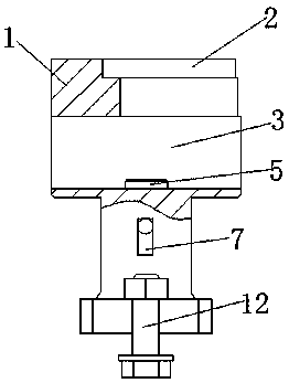
[0025] Example. A device equipped with a transmission shaft with a self-destruct function, consisting of Figure 1~3 As shown, a fixed seat 1 is included, a flat groove 2 is arranged on the top surface of the fixed seat 1, and a part groove 3 is arranged below the flat groove 2. Can refer to for better explanation principle of the present invention Figure 5 ~ Figure 7 , Figure 5 ~ Figure 7 It is a schematic diagram of the size of the structure of the present invention and the labeling of the working surface. In this embodiment, the groove width of the flat groove 2 is C, the depth is H, the groove width is C greater than the width of the flat on the shaft, and the depth H is greater than the height of the flat on the shaft, and is used to install the flat surface on the shaft parts; Part slot ...


PUM


Abstract

The invention discloses a device assembled with a transmission shaft with a self-destruct function. The device comprises a fixed base, a flat groove is formed in the top face of the fixed base, and apart groove is arranged below the flat groove. The device can be assembled with the transmission shaft with the self-destruct function, during assembling, the stress of the transmission shaft can be changed, and the advantage of ensuring the service life of the transmission shaft is achieved.

Description

technical field [0001] The invention relates to the field of assembling a self-destruction transmission shaft, in particular to a device for assembling a transmission shaft with a self-destruction function. Background technique [0002] In the assembly process of complex components, it is often encountered that there are tightening torque requirements when multiple components with complex shapes are assembled and tightened. This includes the assembly of the transmission shaft with self-destruct function. This kind of structure with self-destruct function transmission shaft is generally designed with holes or shapes. There is a section of the shaft wall on the shaft with a thin thickness, which can withstand tensile force, low torsion, and high strength. Weak, during use, when the torque exceeds a certain limit, it can play a self-destruct function. However, when carrying out the assembly of this type of transmission shaft at present, it is as follows Figure 4 After the out...

Claims


Application Information

Patent Timeline
Patent Type & Authority Applications(China)
IPC IPC(8): B25B27/14
CPCB25B27/14
Inventor 张再力袁涛江浩张元博李艳芬李怡钱春旸
Owner GUIZHOU HONGLIN MACHINERY
Why Eureka
Try Eureka