Processing method of optical imaging structure
A processing method and optical imaging technology, which is applied in the field of manufacturing technology, can solve the problems that affect the light transmittance of projection screens and cannot be used to process super-large projection screens, and achieve the effects of strong versatility, strong practicability, and simple operation
- Summary
- Abstract
- Description
- Claims
- Application Information
AI Technical Summary
Problems solved by technology
Method used
Image

Examples
Embodiment 1
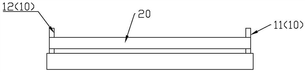
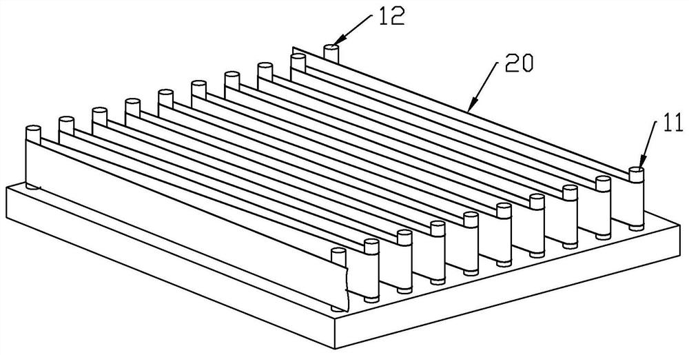
[0070] Such as Figure 1 to Figure 4 As shown, in step S1 , the uprights 10 include two rows of uprights 10 : a first row of uprights 11 and a second row of uprights 12 . A plurality of uprights 10 are respectively arranged in the first row of uprights 11 and the second row of uprights 12 . The first row of uprights 11 and the second row of uprights 12 are relatively spaced apart, and the distance between them is related to the size of the projection screen. The first row of columns 11 and the second row of columns 12 are used to set a functional belt 20, which can be used to process a large-scale optical imaging structure, that is, a projection screen or the basic structure of a projection screen, when the distance between them is relatively large. ; When the distance between them is small, it can be used to process small-sized optical imaging structures.
[0071] The number of uprights 10 in the first row of uprights 11 and the second row of uprights 12 can be set as requi...
Embodiment 2
[0110] Such as Figure 20 ~ Figure 22 As shown, the processing method for the optical imaging structure of this embodiment can be used to manufacture an air-imaging optical imaging structure.
[0111] Such as Figure 20 ~ Figure 22 As shown, in step S1 , the uprights 10 include four rows of uprights 10 : a first row of uprights 11 , a second row of uprights 12 , a third row of uprights 13 and a fourth row of uprights 14 . Several columns 10 are respectively arranged in the four rows of columns. The first row of uprights 11 and the second row of uprights 12 are relatively spaced apart, and the third row of uprights 13 and fourth row of uprights 14 are relatively spaced apart, and the distance between them is related to the size of the optical imaging structure. Between the first row of columns 11 and the second row of columns 12, between the third row of columns 13 and the fourth row of columns 14 are used to set functional belts 20, which can be used to process large-sized ...
Embodiment 3
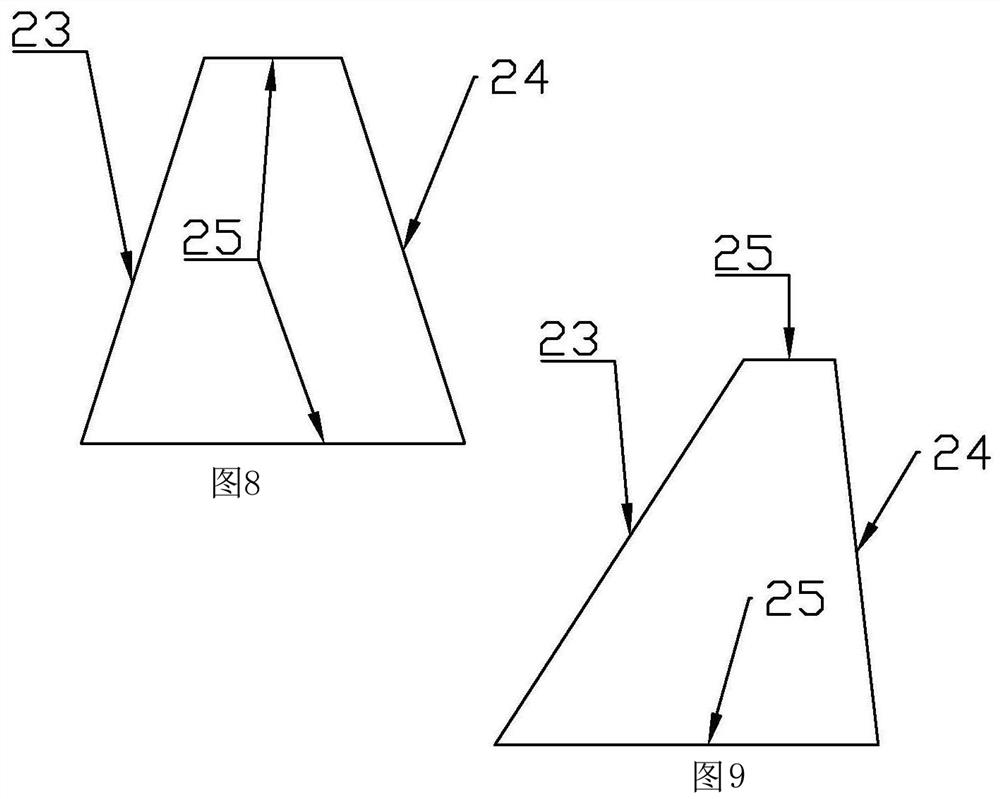
[0139] Such as Figure 23 , Figure 24 As shown, the processing method of the optical imaging structure in this embodiment can be used to manufacture the optical imaging structure with the substrate 40 .
[0140] In step S1 , the columns 10 are disposed on two opposite sides of the substrate 40 . When operating, such as Figure 23 As shown, the substrate 40 is placed on the operating platform, and two rows of columns 10 are arranged on opposite sides of the substrate 40 : a first row of columns 11 and a second row of columns 12 . The first row of uprights 11 and the second row of uprights 12 can be arranged according to needs, which can refer to Example 1, which can be arranged perpendicular to the base material 40 or inclined to the base material 40 . The base material 40 can be made of known materials, for example, it can be glass, plastic sheet, plastic film and so on.
[0141] During specific implementation, the column 10 can be arranged on a mold, and the base materia...
PUM
 Abstract
Description
Claims
Application Information
 - R&D
- Intellectual Property
- Life Sciences
- Materials
- Tech Scout
- Unparalleled Data Quality
- Higher Quality Content
- 60% Fewer Hallucinations
Browse by: Latest US Patents, China's latest patents, Technical Efficacy Thesaurus, Application Domain, Technology Topic, Popular Technical Reports.
© 2025 PatSnap. All rights reserved.Legal|Privacy policy|Modern Slavery Act Transparency Statement|Sitemap|About US| Contact US: help@patsnap.com