
Tamping machine

A tamping machine and the same technology, applied in the direction of roads, road repair, roads, etc., can solve the problems of low soil moisture content, easy to raise large dust, low tamping operation efficiency, etc., to achieve convenient operation, accurate positioning, The effect of increasing soil moisture content

Inactive Publication Date: 2019-10-01
湖北恒诚建设有限公司
View PDF0 Cites 1 Cited by
  • Summary
  • Abstract
  • Description
  • Claims
  • Application Information

AI Technical Summary

Problems solved by technology

[0002] In the existing construction process, the ground needs to be tamped first, and the ground tamping operation is generally carried out by a tamping machine. The existing tamping machine cannot accurately control the drop point of the heavy hammer during the tamping process, resulting in a reduction in the efficiency of the tamping operation. When performing tamping operations on water-deficient ground, due to the low moisture content of the soil, not only the purpose of tamping the ground cannot be achieved, but also it is easy to raise a large amount of dust, and the existing tamping machine is due to the position of the hammer every time. Not the same, after the tamping operation is completed, the ground will have ups and downs, requiring manual secondary trimming

Method used


Image

  • Tamping machine
  • Tamping machine
  • Tamping machine

Examples


Embodiment 1

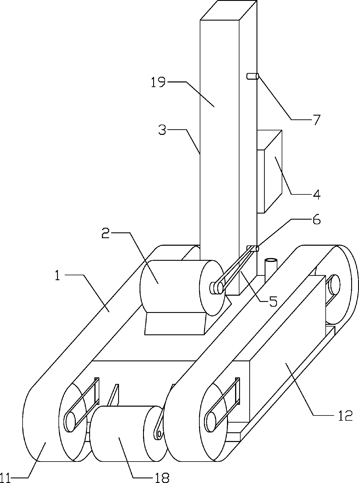
[0028] Such as Figure 1-6 Among them, a tamping machine includes a traveling mechanism 1 and a tamping mechanism 3, said traveling mechanism 1 is provided with a drive motor 2 and a tamping mechanism 3, and the drive motor 2 is connected to the tamping mechanism 3;

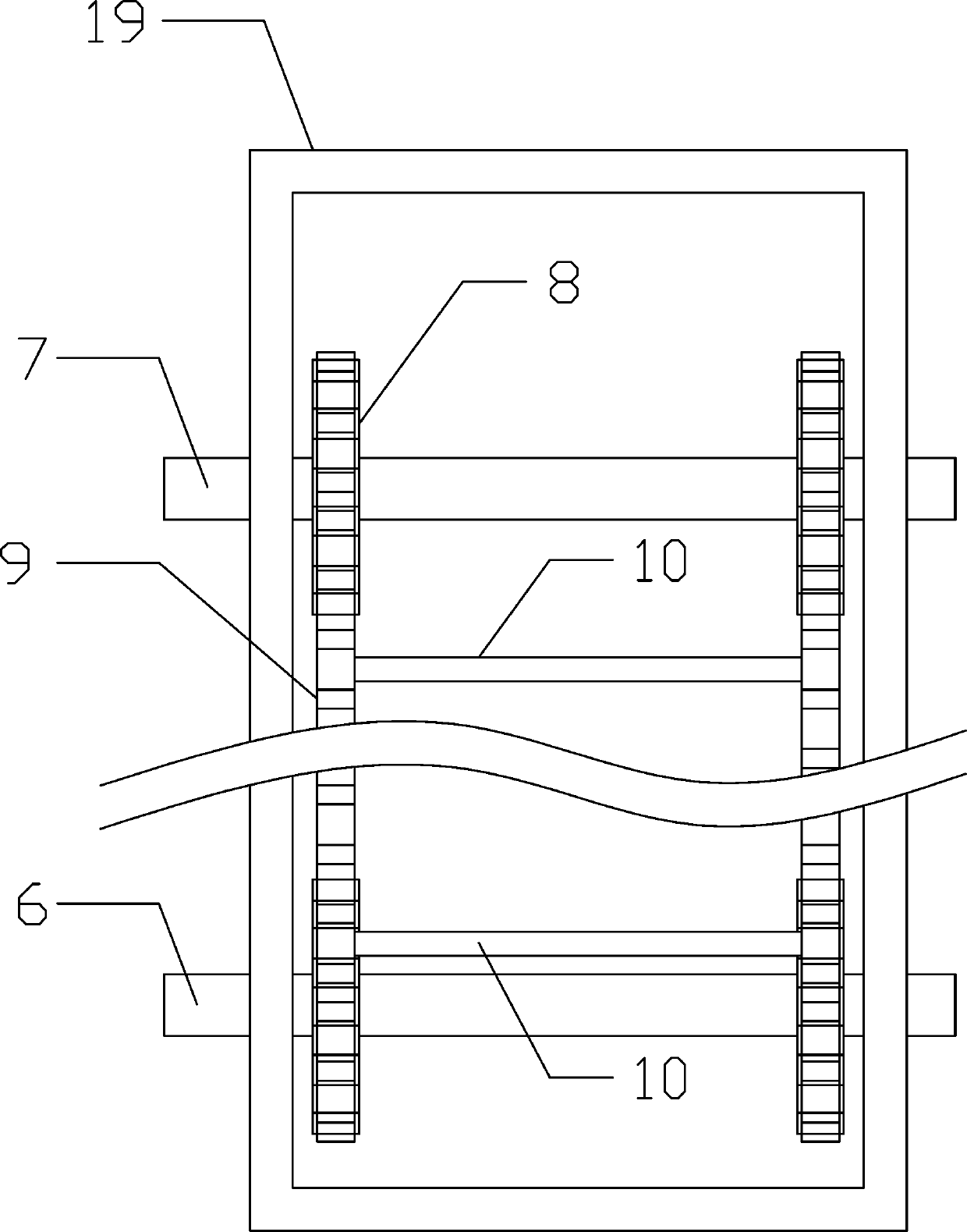
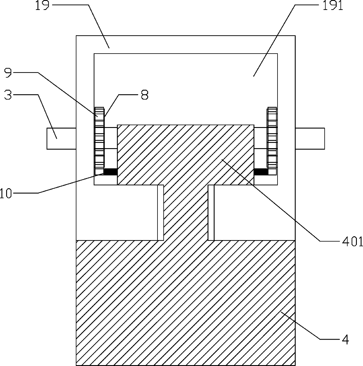
[0029] The tamping mechanism 3 includes a vertically arranged guide rod 19 and a weight 4 arranged on one side of the guide rod 19, the described guide rod 19 is provided with a vertical chute 191, and the described weight 4 A slider 401 is provided on it, and the slider 401 is arranged in the chute 191;

[0030] The upper and lower ends of the guide rod 19 are respectively provided with a first rotating shaft 6 and a second rotating shaft 7, and the first rotating shaft 6 and the second rotating shaft 7 are arranged transversely on the guide rod 19. The first rotating shaft 6 and the second rotating shaft Rotating shaft 7 is provided with gear 8 on the two ends of the part that is positioned at the chute 191 of...

Embodiment 2

[0036] Such as Figure 7 On the basis of Embodiment 1, the base 12 adopts a hollow structure, and there are two chambers in the base 12, one of which is provided with a biaxial motor 13 for driving the crawler belt 11, and the other chamber is a water tank 14 The top of the water tank 14 is provided with a water injection port 15, the water tank 14 is provided with a water pump 16, and the water pump 16 is provided with an outlet pipe 17, and one end of the water outlet pipe 17 is connected with the water pump 16, and the other end passes through the end face of the base 12 and extends to the outside of the end face.

[0037] In a preferred solution, the water tank 14 is arranged at one end close to the base 12 of the tamping mechanism 3 , and the water outlet end of the water outlet pipe 17 is arranged directly below the weight 4 .

[0038] The specific working principle of this device is as follows:

[0039] Move the device to the position where ramming is required, turn on...


PUM


Abstract

The invention discloses a tamping machine. The tamping machine comprises a walking mechanism and a tamping mechanism. A driving motor and the tamping mechanism are arranged on the walking mechanism, the driving motor is connected with the tamping mechanism, the tamping machine comprises a guide rod which is vertically arranged, and a heavy punch arranged on one side of the guide rod, a vertical sliding groove is formed in the guide rod, a sliding block is arranged on the heavy punch, the sliding block is arranged in the sliding groove, through the above structure, effective tamping on the ground is achieved, after tamping work, the ground is leveled, the work quality is ensured, in addition, the tamping point is subjected to watering, the soil humidity of the tamping point is improved, theground tamping is further ensured, and the forceful condition is provided for the subsequent construction.

Description

technical field [0001] The invention relates to the field of road construction equipment, in particular to a rammer. Background technique [0002] In the existing construction process, the ground needs to be tamped first, and the ground tamping operation is generally carried out by a tamping machine. The existing tamping machine cannot accurately control the drop point of the heavy hammer during the tamping process, resulting in a reduction in the efficiency of the tamping operation. When performing tamping operations on water-deficient ground, due to the low moisture content of the soil, not only the purpose of tamping the ground cannot be achieved, but also it is easy to raise a large amount of dust, and the existing tamping machine is due to the position of the hammer every time. Not the same, after the tamping operation is completed, the ground will have ups and downs, requiring manual secondary finishing. Contents of the invention [0003] The technical problem to be...

Claims


Application Information

Patent Timeline
IPC IPC(8): E01C19/41
CPCE01C19/41
Inventor 佘云波滕存五
Owner 湖北恒诚建设有限公司
Learn More