
Novel winding motor stator

A winding and stator technology, which is applied in the field of drive motors for new energy vehicles, can solve the problems of different total lengths of copper wires, unbalanced resistance, and differences in coil inductance, etc., and achieves less demand for production line equipment, less land occupation, and improved motor performance. Effect

Pending Publication Date: 2019-09-27
ZHEJIANG FOUNDER MOTOR
View PDF0 Cites 1 Cited by
  • Summary
  • Abstract
  • Description
  • Claims
  • Application Information

AI Technical Summary

Problems solved by technology

[0002] With the rapid development of new energy vehicle technology, the performance requirements for drive motors are getting higher and higher. At present, there is no batch production of card-issuing flat wire stator products with more than 8 layers in the domestic automobile industry, and the current domestic 4-layer and 6-layer Most of the flat wire stator windings are connected in parallel with two branches, so it is difficult to greatly improve the performance of the product. Increasing the number of branches can greatly improve the performance of the motor, but the stator with multi-branch windings has the following problems:
Due to the inconsistency of the diameters of the layers, that is, the inconsistency of the arc at the end of each layer of copper wires, the accumulation of the number leads to different total lengths of the branch copper wires, resulting in unbalanced resistance
[0004] 2. Due to the influence of the distribution of the temperature field, the unbalance of the resistance, the superposition of the influence of the skin effect and the proximity effect, the inductance of the coils of each layer is also different
[0005] 3. In a group of adjacent slots of the same phase, due to the uneven distribution of each branch, there is a circulating current between the conductors, which reduces the efficiency of the motor

Method used


Image

  • Novel winding motor stator

Examples


Embodiment Construction

[0017] The following describes in detail the embodiments of the present invention, examples of which are illustrated in the accompanying drawings, wherein the same or similar reference numerals refer to the same or similar elements or elements having the same or similar functions throughout. The embodiments described below with reference to the accompanying drawings are exemplary, and are intended to explain the present invention and should not be construed as limiting the present invention.

[0018] In order to make the objectives, technical solutions and advantages of the present invention clearer, the present invention will be further described in detail below with reference to the accompanying drawings and embodiments. It should be understood that the specific embodiments described herein are only used to explain the present invention, but not to limit the present invention.

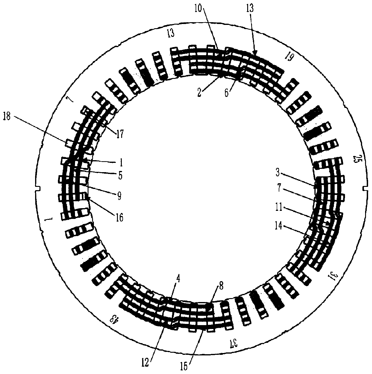
[0019] like figure 1 As shown, a stator of a novel winding motor includes a hollow cylindrical s...


PUM


Abstract

The invention relates to a driving motor for a new energy automobile and particularly relates to a novel winding motor stator. The novel winding motor stator includes a hollow cylindrical stator core body and a stator coil, wherein the stator core body has multiple axially penetrating stator slots formed on a radial inner surface of the stator core body and spaced apart in a circumferential direction of the stator core body, the stator coil is formed by hair clips, the hair clips form first-to-2nth layers arranged in order from the inside to the outside in the radial direction of the stator core body in the stator slots of the stator core body, the n is a natural number, two effective straight segments of each hair clip are respectively placed in odd and even layers of different stator slots, twisting directions of copper wires of twisted ends of the hair clips placed at the odd and even layers at are opposite, and twisting angles are the same, the hair clips and hairpins form multiple branches, and each branch contains all the layers. The novel winding motor stator is advantaged in that through increasing the quantity of branches, motor performance is greatly improved.

Description

technical field [0001] The invention relates to a drive motor for a new energy vehicle, in particular to a stator of a novel winding motor. Background technique [0002] With the rapid development of new energy vehicle technology, the performance requirements for drive motors are getting higher and higher. At present, there is no mass production of card-issued flat wire stator products with more than 8 layers in the domestic automotive industry, and there are currently 4 layers and 6 layers in China. Most of the flat wire stator windings are connected in parallel with two branches, which is difficult to greatly improve the performance of the product. Increasing the number of branches can greatly improve the performance of the motor. However, the stator of the multi-branch winding has the following problems: [0003] 1. When the number of conductors in the straight section of each branch is the same, the resistance imbalance is mainly caused by the two ends of the copper wire...

Claims


Application Information

Patent Timeline
Patent Type & Authority Applications(China)
IPC IPC(8): H02K3/04H02K3/12H02K3/28H02K3/02
CPCH02K3/02H02K3/04H02K3/12H02K3/28H02K2213/03Y02B10/30
Inventor 吴从波
Owner ZHEJIANG FOUNDER MOTOR
Learn More