
Device for locating mold

A technology of a mold and a limit piece, which is applied in the field of mold positioning devices, can solve the problems of inconvenient installation of the positioning device, inconvenience, change the length of the guide column, etc., and achieves the effects of simple structure, convenient operation and convenient use.

Inactive Publication Date: 2019-09-27
GUIZHOU UNIV
View PDF4 Cites 0 Cited by
  • Summary
  • Abstract
  • Description
  • Claims
  • Application Information

AI Technical Summary

Problems solved by technology

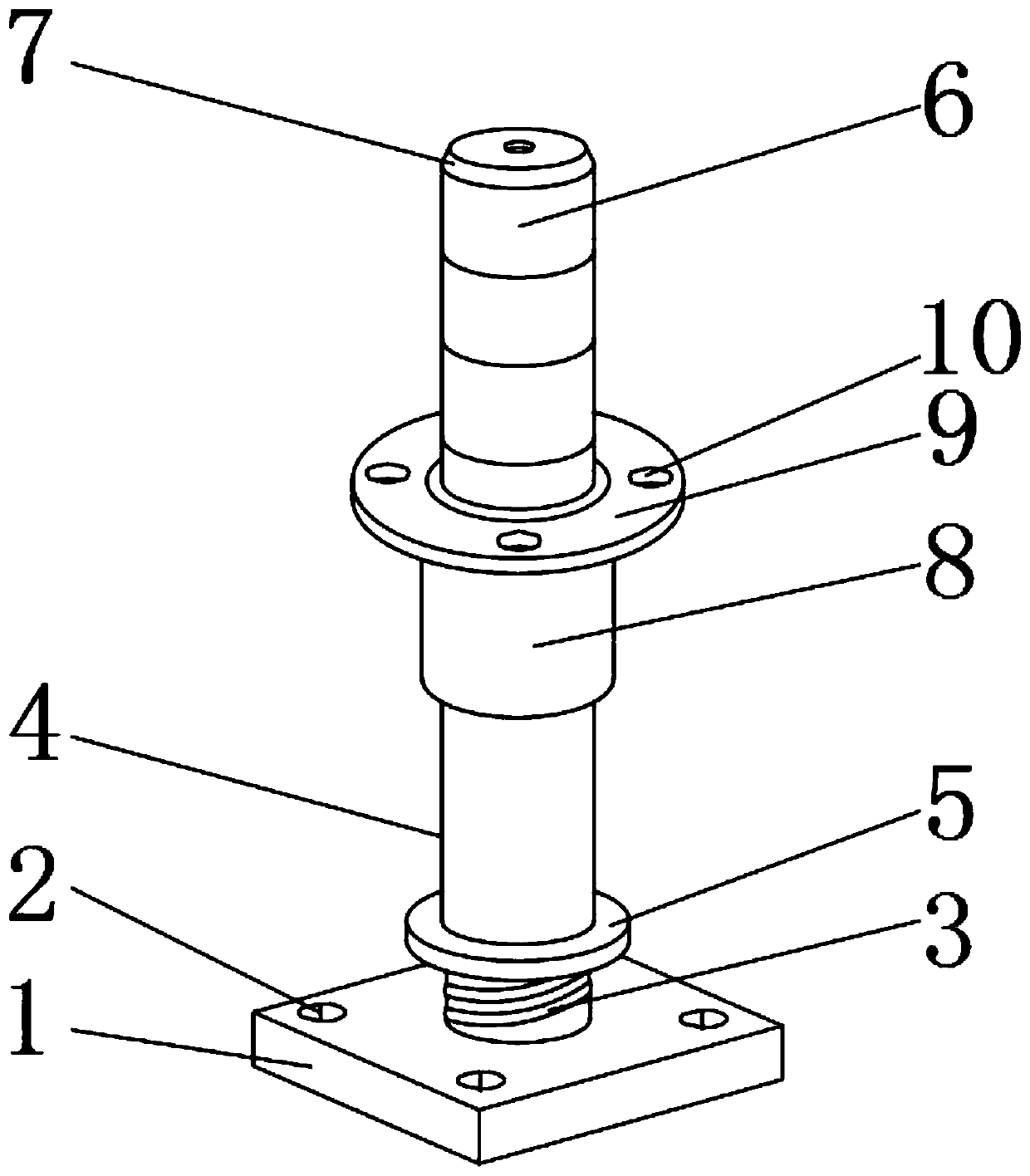
[0002] The mold positioning device is a device used to position the mold. The mold is divided into an upper mold and a lower mold. Positioning is required between the upper mold and the lower mold. The purpose of the mold positioning device is to guide the upper mold and the lower mold. Parts that fit in the correct position are indispensable objects in the mold, but the existing mold positioning devices have certain deficiencies that need to be improved; the existing mold positioning devices have certain disadvantages in use. First of all, the existing positioning device is inconvenient to install, and secondly, the length of the guide column is fixed. When installing different molds, it needs to be customized, and it is not convenient for people to change the length of the guide column. There are certain adverse effects, for this reason, we propose a device for mold positioning

Method used


Image

  • Device for locating mold
  • Device for locating mold
  • Device for locating mold

Examples


Embodiment Construction

[0017] In order to make the technical means, creative features, goals and effects achieved by the present invention easy to understand, the present invention will be further described below in conjunction with specific embodiments.

[0018] In the description of the present invention, it should be noted that the terms "upper", "lower", "inner", "outer", "front end", "rear end", "both ends", "one end", "another end" The orientation or positional relationship indicated by etc. is based on the orientation or positional relationship shown in the drawings, and is only for the convenience of describing the present invention and simplifying the description, rather than indicating or implying that the referred device or element must have a specific orientation, use a specific Azimuth configuration and operation, therefore, should not be construed as limiting the invention. In addition, the terms "first" and "second" are used for descriptive purposes only, and should not be understood ...


PUM


Abstract

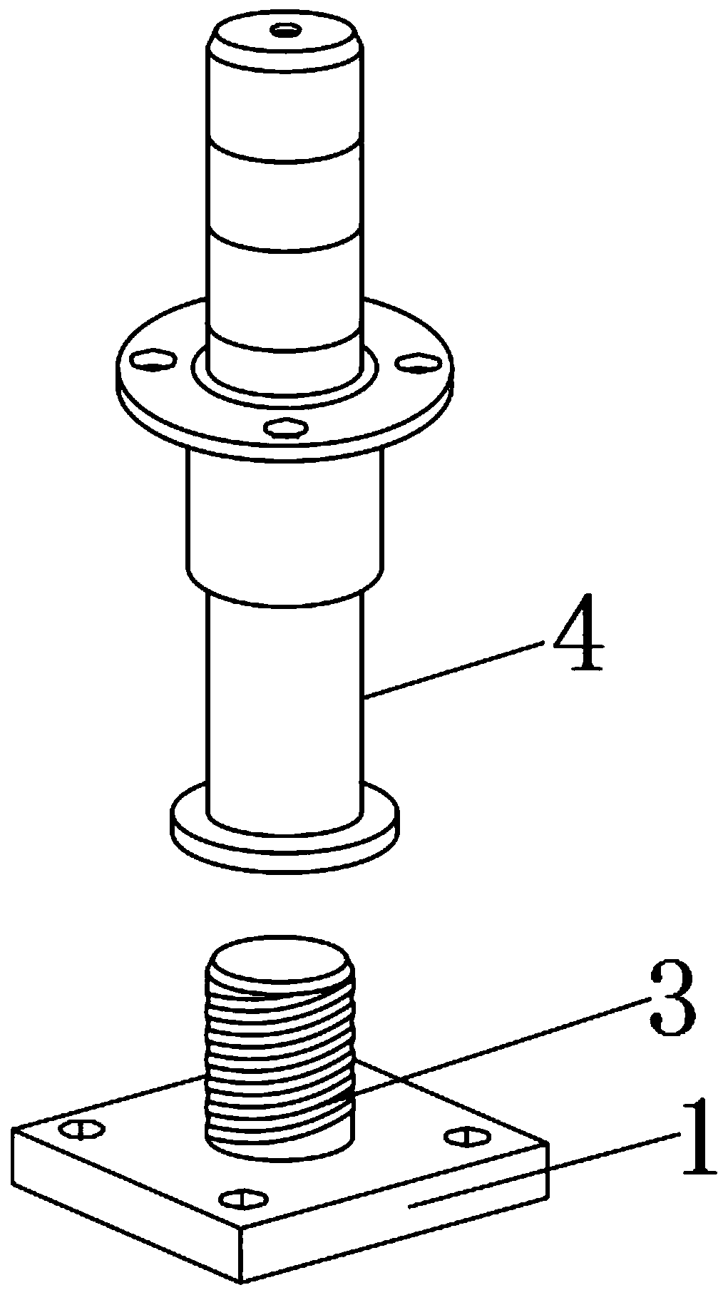
The invention discloses a device for locating a mold. The device for locating the mold comprises a base sheet. First through holes are formed in positions of four corners of the upper surface of the base sheet correspondingly. A fixing bolt is fixedly installed on the upper portion of the base sheet, and a guiding column is arranged outside the fixing bolt in a sleeving manner. A limiting piece is fixedly installed at the bottom end of the guiding column. A top cover is arranged at the top end of the guiding column. Chamfering is arranged in the edge position of the upper surface of the top cover. A guide sleeve is arranged outside the guiding column in a sleeving manner, and a fixing piece is fixedly installed on the top of the guide sleeve. Second through holes are formed in the upper surface of the fixing piece. According to the device for locating the mold, the fixing bolt, a blind hole and connecting guiding columns are arranged; firstly, it is convenient for people to install the locating device on an upper mold and a lower mold, and the use is more convenient; and secondly, it is convenient for people to change the length of the guiding column aiming at different molds, the application range is expanded, and better use prospect is brought about.

Description

technical field [0001] The invention relates to the field of positioning devices, in particular to a device for positioning a mold. Background technique [0002] The mold positioning device is a device used to position the mold. The mold is divided into an upper mold and a lower mold. Positioning is required between the upper mold and the lower mold. The purpose of the mold positioning device is to guide the upper mold and the lower mold. Parts that fit in the correct position are indispensable objects in the mold, but the existing mold positioning devices have certain deficiencies that need to be improved; the existing mold positioning devices have certain disadvantages in use. First of all, the existing positioning device is inconvenient to install, and secondly, the length of the guide column is fixed. When installing different molds, it needs to be customized, and it is not convenient for people to change the length of the guide column. There are certain adverse effects...

Claims


Application Information

Patent Timeline
Patent Type & Authority Applications(China)
IPC IPC(8): B29C33/30
CPCB29C33/30
Inventor 胡威威李伟刘丁孔谭蕴赵丰停
Owner GUIZHOU UNIV
Learn More