
A multi-axis rigid-flexible coupling motion platform

A motion platform, rigid-flexible coupling technology, applied in the direction of workbench, metal processing equipment, metal processing machinery parts, etc., can solve problems such as fracture, mechanism crack, limited application, etc., achieve large working area, low cost, and wide application range Effect

Active Publication Date: 2022-02-25
GUANGDONG UNIV OF TECH
View PDF12 Cites 0 Cited by
  • Summary
  • Abstract
  • Description
  • Claims
  • Application Information

AI Technical Summary

Problems solved by technology

The working principle of the above-mentioned flexible hinges makes the motion platform based on the typical flexible hinge guide mechanism mainly suitable for light load occasions, which limits its application in heavy load occasions
In addition, due to the repeated deformation of the flexible hinge for a long time during the movement, it is easy to cause cracks or even breakage of the guiding mechanism

Method used


Image

  • A multi-axis rigid-flexible coupling motion platform
  • A multi-axis rigid-flexible coupling motion platform
  • A multi-axis rigid-flexible coupling motion platform

Examples


Embodiment 1

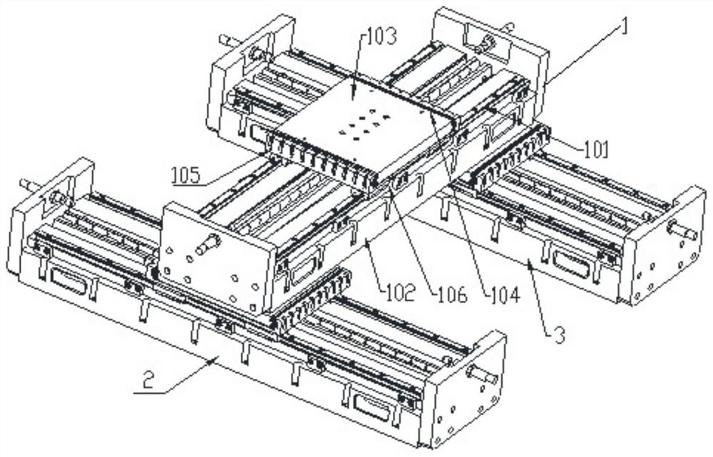
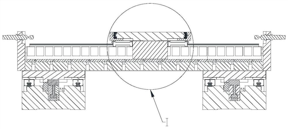
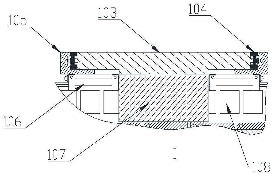
[0033] Such as Figure 1-3 As shown, a multi-axis rigid-flexible coupling motion platform, the multi-axis rigid-flexible coupling motion platform includes: three single-axis rigid-flexible coupling motion platforms, respectively the first single-axis rigid-flexible coupling motion platform 1, the second single-axis Rigid-flexible coupling motion platform 2 and the third single-axis rigid-flexible coupling motion platform 3, each single-axis rigid-flexible coupling motion platform includes: linear guide rail 101, base 102, core motion platform 103, bearing rigidity enhanced flexible hinge group 104 , The rigid frame 105 of the motion platform, the linear guide rail slider 106, the first driver 107 (ie, the linear motor mover), and the linear motor stator 108 (magnetic block). Among them, the core motion platform 103, the bearing rigidity enhanced flexible hinge group 104 and the motion platform rigid frame 105 form a rigid-flexible coupling platform; the first driver 107 (ie, t...

Embodiment 2

[0039] Example two such as Figure 11-12 As shown, it is also a multi-axis rigid-flexible coupling motion platform, including: two single-axis rigid-flexible coupling motion platforms: a first single-axis rigid-flexible coupling motion platform and a second single-axis rigid-flexible coupling motion platform. The structure of each single-axis rigid-flexible coupling motion platform is the same as that of the single-axis rigid-flexible coupling motion platform in Embodiment 1, including: the first core motion platform B1, the first rigid frame of the motion platform B2, the first bearing rigidity enhanced flexibility Hinge group B3, first linear guide rail B4, first linear guide rail slider B5, first base B6, first linear motor stator (magnetic block) B13, second bearing rigidity enhanced flexible hinge group B7, second Core motion platform B8, second motion platform rigid frame B9, second base B10, second linear guide rail slider B11, second linear guide rail B12, second linea...


PUM


Abstract

The present invention relates to a multi-axis rigid-flexible coupling motion platform. The multi-axis rigid-flexible coupling motion platform includes: three single-axis rigid-flexible coupling motion platforms, and each of the single-axis rigid-flexible coupling motion platforms includes: a linear guide rail , base, core motion platform, load-bearing rigidity enhanced flexible hinge group, motion platform rigid frame, linear guide rail slider, linear drive; one end of the base of the first single-axis rigid-flexible coupling motion platform is connected to the second rigid The core motion platform of the flexible coupling motion platform is connected, and the other end of the base of the first single-axis rigid-flexible coupling motion platform is connected with the core motion platform of the third single-axis rigid-flexible coupling motion platform. The multi-axis rigid-flexible coupling motion platform has a large working area and strong bearing capacity, and can flexibly build various large-stroke high-precision multi-axis motion platforms with the required number of axes according to specific requirements.

Description

technical field [0001] The invention relates to the technical field of high-precision motion, and more specifically relates to a multi-axis rigid-flexible coupling motion platform. Background technique [0002] Flexible hinges are widely used in the design of precision motion platforms due to their frictionless and lubrication-free properties. In precision motion platforms, flexible hinges are mainly designed as guiding mechanisms. In the precision motion platform, when the motion platform starts, stops and micro-displacement feeds, as a frictionless motion pair, the flexible hinge mainly realizes the motion through its own elastic deformation. The above-mentioned working principle of the flexible hinge makes the motion platform based on the typical flexible hinge guide mechanism mainly suitable for light load occasions, which limits its application in heavy load occasions. In addition, due to the repeated deformation of the flexible hinge for a long time during the moveme...

Claims


Application Information

Patent Timeline
Patent Type & Authority Patents(China)
IPC IPC(8): B23Q1/25B25H1/00
CPCB23Q1/25B25H1/00
Inventor 杨志军袁伟涛苏丽云白有盾陈新
Owner GUANGDONG UNIV OF TECH
Learn More