DF 37 micrometer flack direction locking device based on worm sleeve and control method
A technology of locking device and worm sleeve, applied in the direction of devices affecting weather conditions, botanical equipment and methods, applications, etc., can solve problems such as limitations, and achieve the effects of low cost, easy maintenance and repair, and simple structure of the lock body
- Summary
- Abstract
- Description
- Claims
- Application Information
AI Technical Summary
Problems solved by technology
Method used
Image
Examples
Embodiment 1
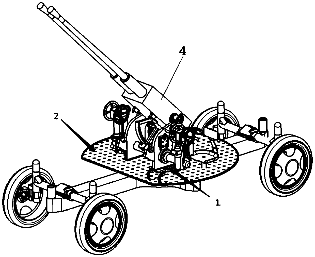
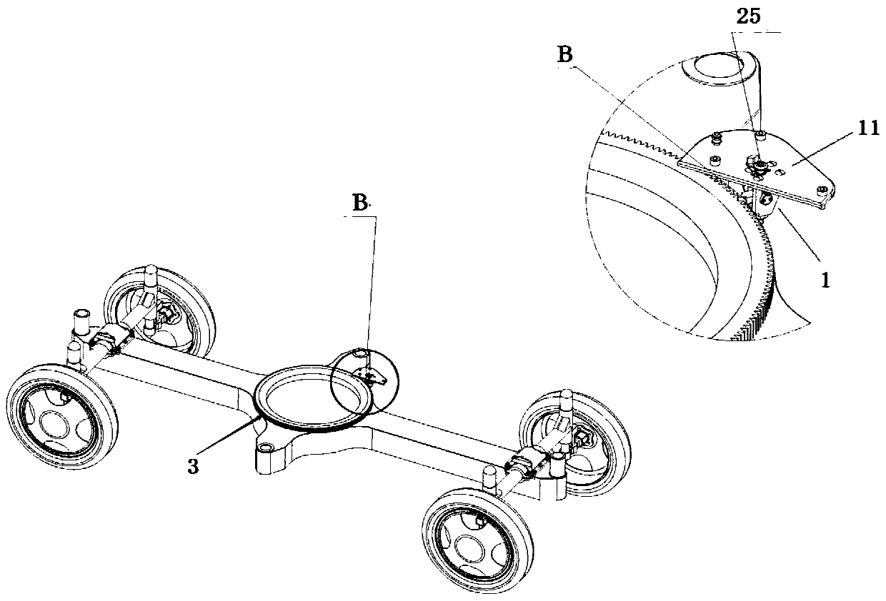
[0031] according to figure 1 and figure 2 It can be seen that a DF37mm anti-aircraft gun direction locking device based on a worm sleeve includes a primary cannon 4 meshing with the direction gear ring 3, the bottom of the primary cannon 4 is fixedly connected to the cannon pan 2, and the direction machine locking device 1 includes a cannon that is fixedly connected to the cannon pan 2. The cover plate 11 and the steering gear locking device 1 are fixed below the cannon plate 2, and the space is narrow and small, which is unfavorable for manually implementing the destruction of the lock body.
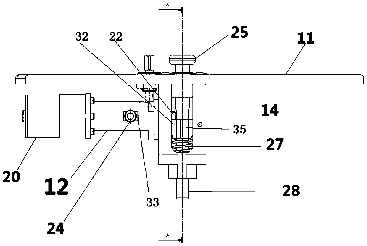
[0032] Such as image 3 The steering lock device 1 includes a lock body 14 and a motor assembly. The lock body 14 is installed below the cover plate 11. The lock body 14 has a hollow portion, and the cover plate 11 is provided with a through hole connecting the hollow portion. The side of the main body 14 is connected with the motor assembly by special bolts. After the lock rod 28 pa...
Embodiment 2
[0038] On the basis of the device in embodiment 1, the outer circumference of the worm sleeve 19 and the inner circumference of the connecting sleeve 12 are all changed into cylindrical universal parts, such as figure 2 , but the circumferential surface of the connecting sleeve 12 is provided with a chute 33, the retaining ring bolt 24 passes through the chute 33, the worm sleeve 19 is connected to the retaining ring 17, and when the retaining ring bolt 24 also adopts a special bolt, the retaining ring 17 is easy to take out, and the worm Cover 19 is easier to process, and retaining ring bolt 24 can prevent worm screw cover 19 from rotating with worm screw 7 when worm screw 7 rotates. Simultaneously owing to being provided with retaining ring bolt 24, under special circumstances, as stepper motor 20 failures or under the situation of power supply interruption, the operator can open the back cover of stepper motor 20, while turning motor shaft 23 rear end rotors with wrench, di...
Embodiment 3
[0040] Both devices of embodiment 1 and embodiment 2 can be normally unlocked according to the following procedures. Such as Figure 6
[0041] When unlocking, after the operator passes the fingerprint verification PCL controller 37 to send an electric control command to the motor driver 39, the stepper motor 20 drives the worm rod 7 to rotate, so that the worm gear sleeve 19 moves backward, and the spring 2 18 is stretched backward under force. Make the lock cylinder 22 and the lock tongue 35 separate and unlock the lock lever 28, the lock lever 28 rises through the reaction force of the spring 1 27 and the lock tongue 35, and breaks away from the contact with the direction gear ring 3. The direction machine gear ring 3 is unlocked, and the direction gear ring Turn normally.
[0042] The principle of electric control is as follows:
[0043] according to Figure 6 It can be seen that a control method for a DF37mm anti-aircraft gun steering locking device comprises the foll...
PUM
 Abstract
Description
Claims
Application Information
 - Generate Ideas
- Intellectual Property
- Life Sciences
- Materials
- Tech Scout
- Unparalleled Data Quality
- Higher Quality Content
- 60% Fewer Hallucinations
Browse by: Latest US Patents, China's latest patents, Technical Efficacy Thesaurus, Application Domain, Technology Topic, Popular Technical Reports.
© 2025 PatSnap. All rights reserved.Legal|Privacy policy|Modern Slavery Act Transparency Statement|Sitemap|About US| Contact US: help@patsnap.com


