Explosion-proof combined permanent magnet electromechanical integrated machine and assembly method

An all-in-one and combined technology, applied in the direction of electromechanical devices, electric components, electrical components, etc., can solve the problem of failure to meet the coal safety requirements of mining equipment, inability to use the underground working environment of coal mines, and difficult maintenance of oil cooling and oil immersion structures, etc. problems, to achieve the effect of saving manpower, saving initial investment, and reducing noise

Active Publication Date: 2021-04-30
TANGSHAN DEBOTE MACHINERY
View PDF1 Cites 0 Cited by
  • Summary
  • Abstract
  • Description
  • Claims
  • Application Information

AI Technical Summary

Problems solved by technology

However, there are the following problems in the application range and use: (1) At present, the built-in electric drum is generally below 90kW with small and medium power and low voltage, and there are basically no products with optimized application structure, high efficiency and high power transmission; (2) Motor, reducer The built-in structure of the device has the problems of difficult maintenance of oil cooling and oil immersion structure (oil leakage problem, etc.), and high maintenance cost; (3) The traditional transmission structure still has the problem of low efficiency, such as the traditional belt conveyor and conveyor belt The transmission efficiency of the system is generally about 70%
The Chinese utility model patent with the application number 201520581361.X discloses a semi-direct drive permanent magnet motor power assembly; in this structure, the reducer casing is connected to the low-speed permanent magnet motor casing and the shaft extension end cover is jointly composed Machine gear lubricating oil chamber, however, this structural design is not independent of each other, cannot meet the coal safety requirements of mining equipment, and cannot be used in the coal mine operating environment

Method used


Image

  • Explosion-proof combined permanent magnet electromechanical integrated machine and assembly method
  • Explosion-proof combined permanent magnet electromechanical integrated machine and assembly method
  • Explosion-proof combined permanent magnet electromechanical integrated machine and assembly method

Examples


Embodiment Construction

[0026] Below in conjunction with accompanying drawing, the present invention will be further described by examples.

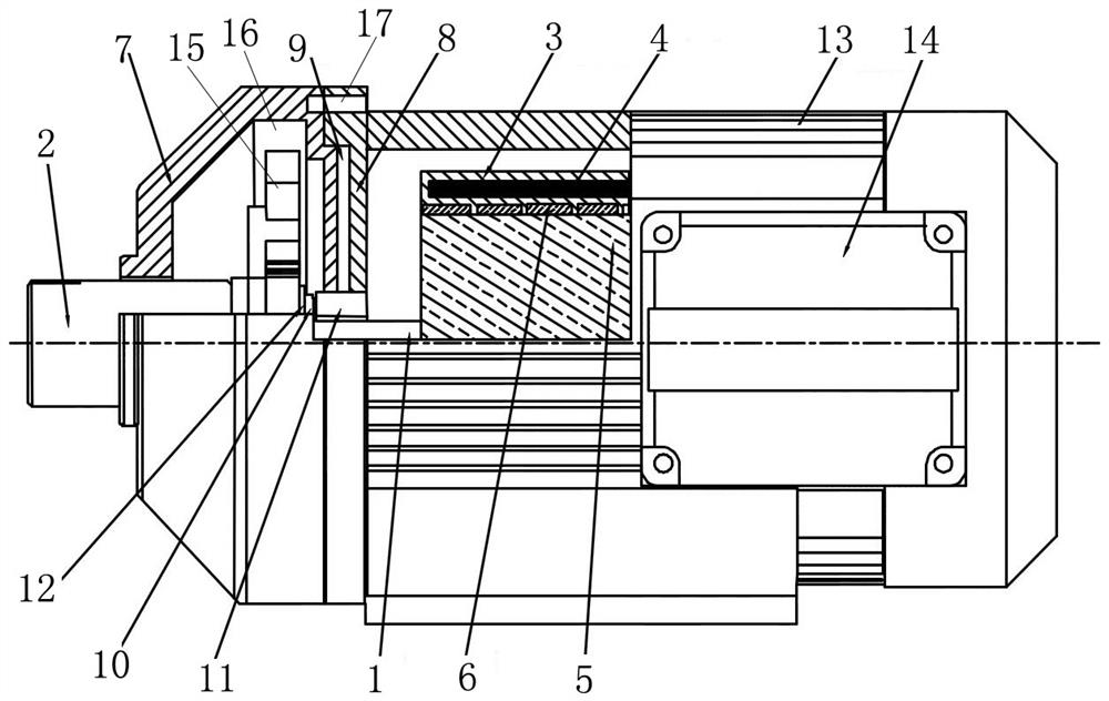
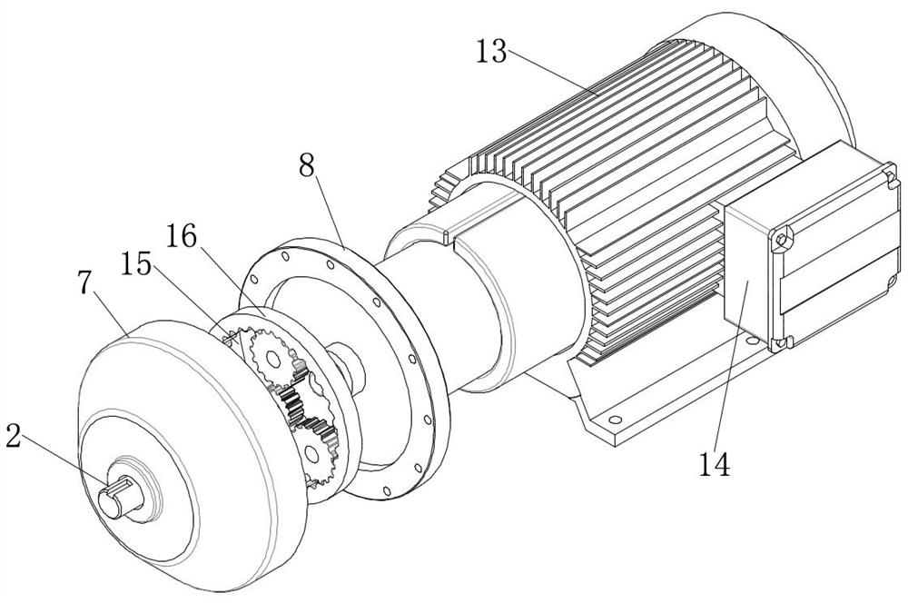
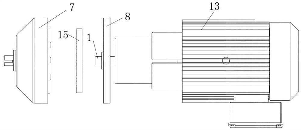
[0027] An explosion-proof combined permanent magnet electromechanical machine, comprising a casing 13, a rotor shaft 1, an output shaft 2, a permanent magnet stator core 3, a stator winding 4, a rotor core 5, a magnetic steel 6 and a planetary reducer 15; The front end cover 8 of the casing 13 is provided with a bearing 11, and the rotor shaft 1 is arranged on the bearing 11; the permanent magnet stator core 3 is arranged inside the casing 13, and the stator winding 4 is arranged on the permanent magnet stator core 3, and the rotor shaft 1 A rotor core 5 is provided on the rotor core 5, and a magnetic steel 6 is provided on the rotor core 5; the planetary reducer 15 is arranged on the reducer base 16, and the input shaft 10 of the reducer is provided with a spline groove 12, and the rotor shaft outside the bearing 11 1. The end part is connected with the reduce...


PUM


Abstract

The invention relates to an explosion-proof combined permanent magnet electromechanical integrated machine and an assembly method, belonging to the technical field of explosion-proof permanent magnet motors. The technical solution is: the planetary reducer (15) is arranged on the reducer base (16), the input shaft (10) of the reducer is provided with a spline groove (12), and the end of the rotor shaft (1) outside the bearing (11) It is connected with the reducer input shaft (10) through a spline, the reducer input shaft and the rotor shaft are concentric, and there is a cavity independent space (9 ); The permanent magnet motor and the planetary reducer are connected as one structure. Beneficial effects of the present invention: the connection between the front end cover of the motor and the base of the reducer is provided with an independent space for the cavity, which conforms to the standard of mine motors, and at the same time improves the working efficiency of reloading, lifting, transportation and other operations.

Description

technical field [0001] The invention relates to an explosion-proof combined permanent magnet electromechanical integrated machine and an assembly method, belonging to the technical field of explosion-proof permanent magnet motors. Background technique [0002] At present, in the industrial electric drive system, the traditional transmission method is the motor-coupling (or hydraulic coupling)-reducer-roller, etc. This typical equipment configuration has been widely used, especially the high-power system, which still adopts the traditional method, which brings many problems to the on-site operation and maintenance. For example: low transmission efficiency, large operation and maintenance workload, high cost, large space required for equipment layout, large initial project investment, etc. As a motor deceleration transmission, its structure is to apply motors, reducers and other components to the power output conversion of belt conveyors and lifting transportation equipment, ...

Claims


Application Information

Patent Timeline
Patent Type & Authority Patents(China)
IPC IPC(8): H02K7/116H02K5/04H02K1/17H02K9/19H02K15/00
CPCH02K1/17H02K5/04H02K7/116H02K9/19H02K15/00
Inventor 杨贵雨
Owner TANGSHAN DEBOTE MACHINERY
Why Eureka
Try Eureka