
A method for reducing the scattering cross section of stealth metasurface radar based on spatial mapping

A technology of radar cross section and space mapping, applied in design optimization/simulation, combustion engine, internal combustion piston engine, etc., can solve a lot of time and resource problems, and achieve the effect of reducing optimization time, improving optimization efficiency, and saving accuracy

Active Publication Date: 2022-08-09
NANJING UNIV OF SCI & TECH
View PDF2 Cites 0 Cited by
  • Summary
  • Abstract
  • Description
  • Claims
  • Application Information

AI Technical Summary

Problems solved by technology

In the past, the research work on the scattering characteristics of stealth metasurfaces mostly relied on numerical algorithms or commercial software based on numerical algorithms, which required a lot of time and resources

Method used


Image

  • A method for reducing the scattering cross section of stealth metasurface radar based on spatial mapping
  • A method for reducing the scattering cross section of stealth metasurface radar based on spatial mapping
  • A method for reducing the scattering cross section of stealth metasurface radar based on spatial mapping

Examples


Embodiment 1

[0056] Combine figure 1 , The invention is a stealth super surface radar scattering section (RCS) reduction method based on spatial mapping (SMM '). The specific steps are:

[0057] Step 1. In this embodiment, two PEC micro -stranded patch units are designed to form a stealth ultra -surface. The medium of the unit is a cube medium. The size: 50mm in length, 50mm wide, 10mm high, and 2.2 medium rate. The bottom of the two units is the bottom surface of the PEC, and the top is a square PEC patch with a edge length of 20mm and 40mm, named "0" and "1" unit. Establish a stealth ultra -surface composed of M × N yuan PEC micro -stranded patch unit, and rows and N column are closely discharged. Taking the center point of the center point of the PEC micro-stranded patch unit, the first super surface unit of the first line is the X-axis, and the 1st super surface unit is-y axis. The Z axis creates the coordinate system XYZ, and sets up a little pitch angle in the coordinate system XYZ is θ,...

Embodiment 2

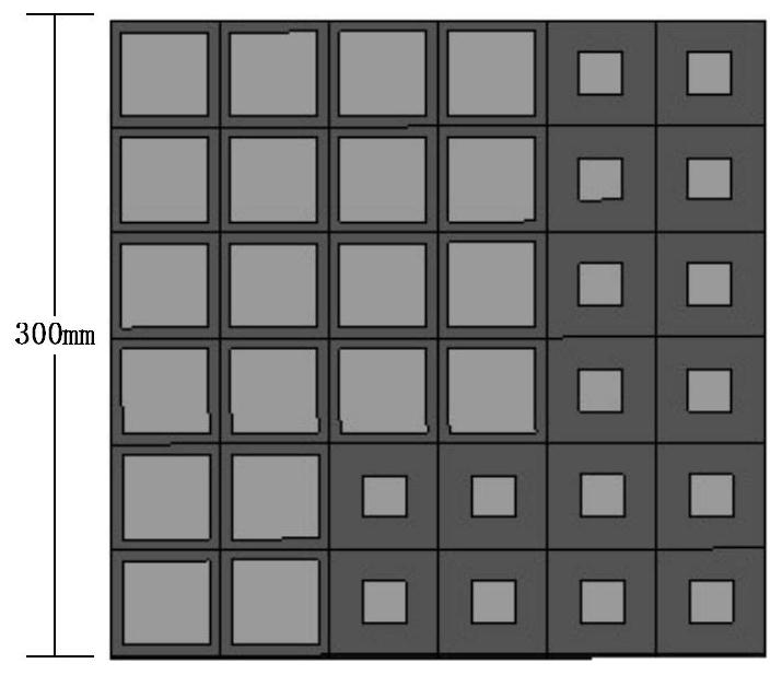
[0102] In order to verify the correctness and effectiveness of this method, the stealth super surface is analyzed below figure 1 Two units are randomly discharged Figure 4 The 12 × 12 yuan plane array, that is, m = 12, n = 12, and the incident wave is selected as a plane wave vertical irradiation of 3GHz. Examples are implemented on personal computers with a main frequency of 2.83GHz and 8GB of memory.

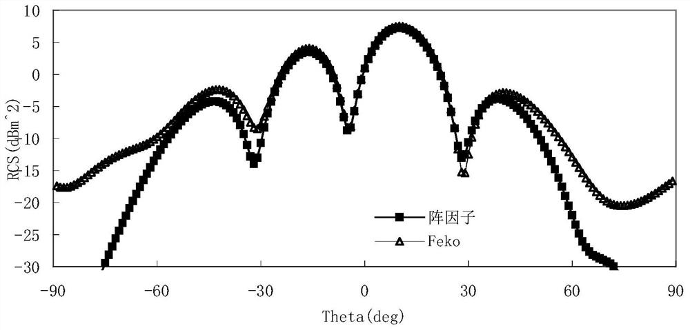
[0103] Figure 5 Indicates the super surface array optimized by the invention algorithm. Depend on Image 6 The optimization result can be seen that when the PHI is 0 °, the calculation value of most of the angle of RCS of the angle-90 ° ≤ ≤ 90 °. The super surface composed of the two patch units of the invention design is significantly reduced compared to the RCS of the plane of the PEC. This fully proves the effectiveness of the super surface composed of the two super surface units designed by the present invention. After the current invention algorithm is optimized, the super su...


PUM


Abstract

The present invention disclosed a method of stealth super surface radar scattering section reduction method based on space mapping.First of all, establish a stealth super surface model, so that the uniform plane waves are irradiated on the stealth ultra -surface to determine the total scattering field of the stealth super surface; then calculate the rcs obtained by the first stealth ultra -surface based on the coupling array factors, as the stealth ultra -surface SMThe rough model of the algorithm optimizes the rough model and finds the optimal solution of the rough model. Finally, the mapping relationship establishes the mapping relationship in the upper and step 3 of the rough model to obtain the prediction parameters of the model to obtain the fine model.If it is not satisfied, iterates the mapping relationship between the rough model parameters and the fine model parameters, and the response to the obtained response meets the design requirements.The method of the present invention optimizes the discharge of the two units to form a super surface. In the case of determining the size of the super surface array, the RCS reduction has been increased while saving time and memory.

Description

Technical field [0001] The invention is the field of super surface radar scattering section reduction technology, especially a space -based stealth super surface radar scattering section reduction method. Background technique [0002] In the modern war, radar played a pivotal role, and any military goal faced a serious threat to "discovery is destroyed." However, if the military target has a certain anti -radar hidden performance, it can increase the probability of survival on the battlefield, thereby increasing the survivability of the battlefield. The purpose of the radar scattering sectional area (RCS) is to reduce the RCS of military targets through various effective technical measures. [0003] To design and optimize the large stealth super surface, it is necessary to use a powerful electromagnetic scattering calculation method. In the past, research on the characteristics of stealth super surface scattering characteristics, with the help of a numerical algorithm or commerci...

Claims


Application Information

Patent Timeline
Patent Type & Authority Patents(China)
IPC IPC(8): G06F30/20
CPCG06F30/20Y02T10/40
Inventor 陈如山唐之宣李猛猛丁大志樊振宏韩居正陶诗飞何姿
Owner NANJING UNIV OF SCI & TECH
Learn More