Rotatable bracket for computer dual-screen display
A rotating bracket and dual-screen technology, which is applied in the direction of machines/supports, supporting machines, mechanical equipment, etc., can solve the problem of limiting the space and range of display brackets, occupying office area, not being able to provide horizontal and vertical dual-screen display, multi-directional rotation up and down Reliable and firm fixed connection, easy sharing operation, convenient and quick steering effect
- Summary
- Abstract
- Description
- Claims
- Application Information
AI Technical Summary
Problems solved by technology
Method used
Image
Examples
Embodiment 1
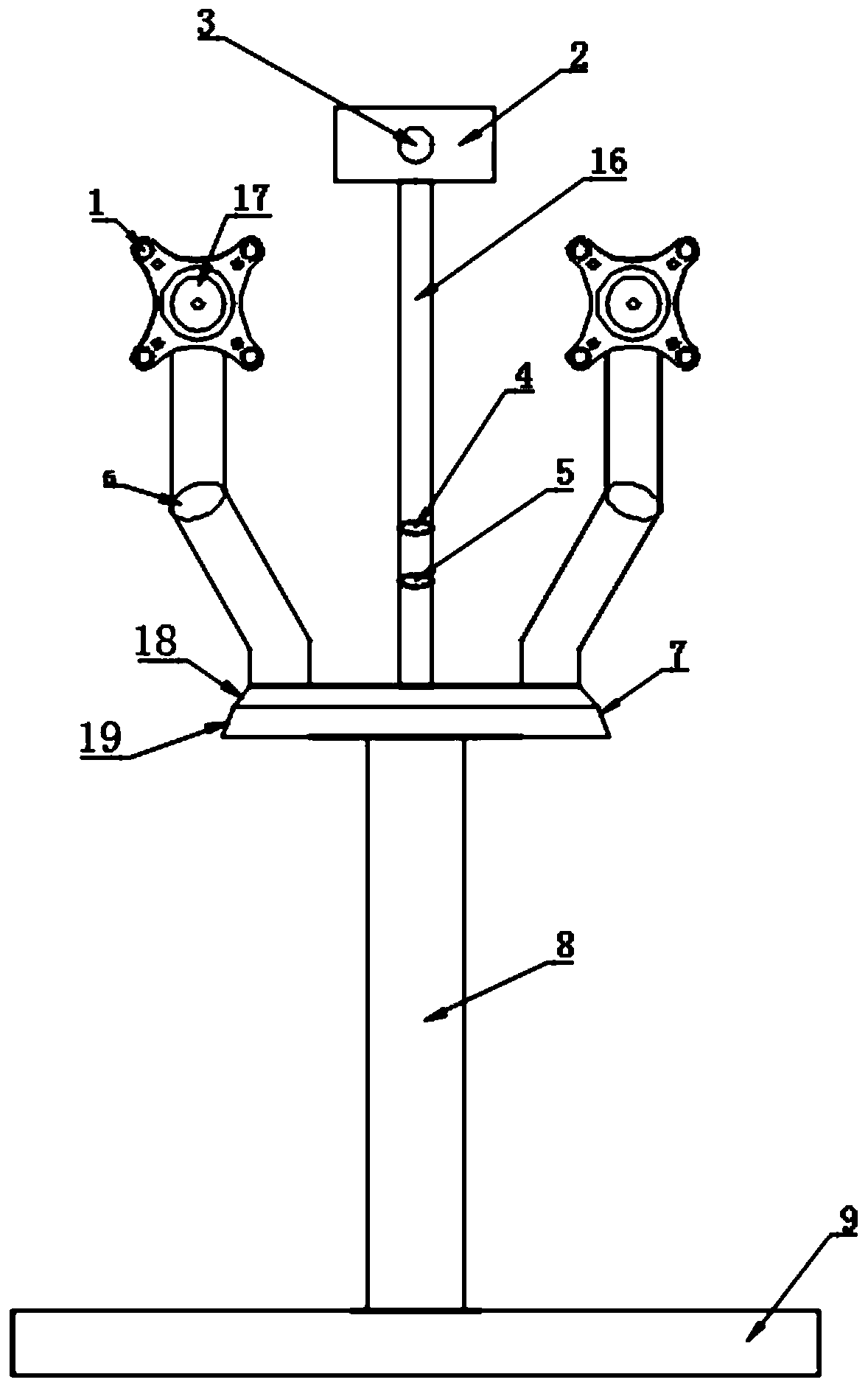
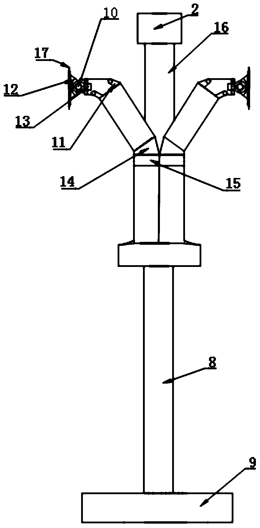
[0026] Embodiment one: if Figure 1-2 As shown, a rotatable support for a computer dual-screen display includes a fixing device, a supporting device and a clamping device, and the fixing device includes a first fixing plate 9, a first telescopic rod 8 and a second fixing plate 7, and the One side of the first fixed plate 9 is provided with the first telescopic rod 8, one end of the first telescopic rod 8 is fixedly connected with the first fixed plate 9, and the other end of the first telescopic rod 8 is connected to the first fixed plate 9. The second fixed plate 7 is fixedly connected, and the side of the second fixed plate 7 away from the first fixed plate 9 is provided with a second telescopic rod 16 and the clamping device, and the clamping device includes a supporting shaft 6 , block 15, bearing connecting rod 13, telescopic plate 14 and several clamping rods, the side of the second fixed plate 7 away from the first telescopic rod is provided with each of the clamping ro...
Embodiment 2
[0027]Embodiment 2: A rotatable bracket for a computer dual-screen display, including a fixing device, a supporting device and a clamping device, the fixing device includes a first fixing plate 9, a first telescopic rod 8 and a second fixing plate 7, the One side of the first fixed plate 9 is provided with the first telescopic rod 8, one end of the first telescopic rod 8 is fixedly connected with the first fixed plate 9, and the other end of the first telescopic rod 8 is connected with the first fixed plate 9. The second fixed plate 7 is fixedly connected, and the side of the second fixed plate 7 away from the first fixed plate 9 is provided with a second telescopic rod 16 and the clamping device, and the clamping device includes a supporting shaft 6. Block 15, bearing connecting rod 13, telescopic plate 14 and several clamping rods, the side of the second fixed plate 7 away from the first telescopic rod is provided with each of the clamping rods, each of the The rod body of t...
Embodiment 3
[0032] Embodiment three: on the basis of embodiment two, as image 3 As shown, the clamping rods are symmetrically arranged on the second fixing plate 7 of this embodiment, and the clamping rods are symmetrically distributed on the second fixing plate 7 , and the two sides of the second fixing plate 7 The clamping rods on the side are arranged facing away from each other, and the setting of the supporting shaft 6 of the clamping rods makes the adjustment process more stable and reliable. At the same time, a structure with a small angle can be formed between adjacent screens to ensure that the adjacent screens will not affect each other. In addition, in this embodiment, the second support rod 16 is provided with several fixing plate structures, which are stacked in sequence. At the same time, each of the fixing plates is also provided with a clamping device, and the clamping device includes an expansion screen, which makes the entire display area larger and facilitates the rot...
PUM
 Abstract
Description
Claims
Application Information
 - Generate Ideas
- Intellectual Property
- Life Sciences
- Materials
- Tech Scout
- Unparalleled Data Quality
- Higher Quality Content
- 60% Fewer Hallucinations
Browse by: Latest US Patents, China's latest patents, Technical Efficacy Thesaurus, Application Domain, Technology Topic, Popular Technical Reports.
© 2025 PatSnap. All rights reserved.Legal|Privacy policy|Modern Slavery Act Transparency Statement|Sitemap|About US| Contact US: help@patsnap.com


