Pre-alignment device and testing equipment

A technology of positioning device and carrier, which is applied in the directions of transportation and packaging, conveyor objects, etc., can solve the problems of troublesome disassembly and replacement of movable limit blocks, many mechanical contacts of the carrier surface, and large damage to the carrier surface, etc. Detection accuracy and detection efficiency, improve pre-alignment accuracy and manual feeding efficiency, and ensure the effect of stable detection

Active Publication Date: 2021-02-09
BOE TECH GRP CO LTD +1
View PDF10 Cites 0 Cited by
  • Summary
  • Abstract
  • Description
  • Claims
  • Application Information

AI Technical Summary

Problems solved by technology

[0003] It is troublesome to disassemble and replace the movable limit block, and it has more mechanical contact with the carrier surface, which will cause greater damage to the carrier surface; in addition, due to the overall manufacturing process, assembly accuracy, material characteristics, etc., the movable limit block There is a certain gap between the contact surface with the carrier, and the flexible display product has the characteristics of ultra-thin, it is very easy for the product to be inserted into the gap between the contact surface when the material is manually loaded, resulting in alignment deviation and Difficulty in personnel operation seriously affects work efficiency

Method used


Image

  • Pre-alignment device and testing equipment
  • Pre-alignment device and testing equipment
  • Pre-alignment device and testing equipment

Examples


Embodiment 1

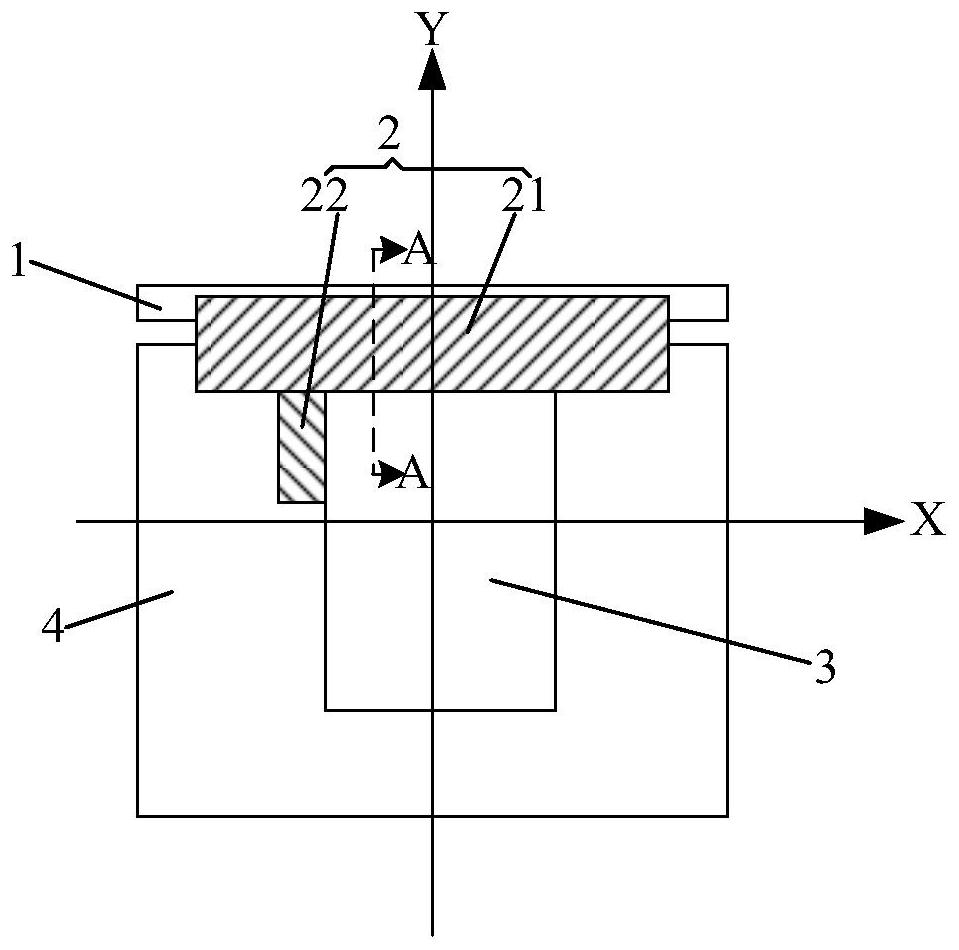
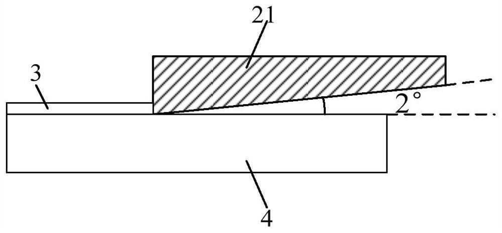
[0026]This embodiment provides a pre-alignment device, such asfigure 1 withfigure 2 As shown, it includes a fixed structure 1 and a pre-aligned structure 2. The pre-aligned structure 2 is movably connected to the fixed structure 1, and the pre-aligned structure 2 is located on the surface of the stage 4 carrying the substrate 3 to be tested in the pre-aligned state, The pre-alignment structure 2 includes a baffle 21 and a stop 22 that respectively define the position of the substrate to be tested in a first direction X and a second direction Y that are perpendicular to each other. In the pre-alignment state, the baffle 21 and the stop 22 It is in line contact with the table surface of the carrier 4, and the line contact part is located at the end of the baffle 21 and the stop 22 that is in contact with the substrate 3 to be tested.

[0027]By making the baffle 21 and the stopper 22 in the pre-aligned state to be in line contact with the surface of the stage 4, compared with the existin...

Embodiment 2

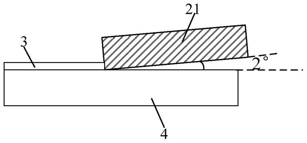
[0039]This embodiment provides a pre-alignment device. The difference from Embodiment 1 is that in this embodiment, in the pre-alignment state, only the baffle or only the stopper is in line contact with the surface of the stage, and the line contact part It is located at the end of the baffle or stop which is in contact with the substrate to be tested.

[0040]In this embodiment, the other structure of the pre-alignment device is the same as that in Embodiment 1, and will not be repeated here.

[0041]The beneficial effects of the embodiment 1-2: the pre-alignment device provided by the embodiment 1-2, by making the baffle and / or the stopper in the pre-alignment state come into line contact with the surface of the stage, compared with the existing Pre-alignment of the substrate to be tested by the contact between the movable limit block and the surface of the stage can relatively reduce or eliminate the gap between the baffle and the surface of the stage and the contact position of the s...

Embodiment 3

[0043]This embodiment provides a detection device used to perform lighting detection on a display substrate, including the pre-alignment device in Embodiment 1 or 2.

[0044]The detection equipment also includes a carrier, which is used for vacuum adsorption and fixation of the display substrate; the pre-alignment device is arranged on one side of the carrier. When performing lighting inspection on the display substrate, fix the pre-alignment device on the side of the stage, and then perform pre-alignment on the manually loaded display substrate. After the pre-alignment is completed, perform the display substrate lighting test.

[0045]By adopting the pre-alignment device in Embodiment 1 or 2, the detection equipment can improve its detection accuracy and detection efficiency, and can also ensure stable detection.


PUM


Abstract

The invention provides a pre-alignment device and detection equipment. The pre-alignment device includes a fixed structure and a pre-alignment structure, the pre-alignment structure is movably connected to the fixed structure, and the pre-alignment structure is located on the stage carrying the substrate to be tested in the pre-alignment state, and the pre-alignment structure includes The baffles and stoppers respectively define the position of the substrate to be tested in the first direction and the second direction perpendicular to each other. In the pre-alignment state, the baffles and / or stoppers are in line contact with the stage surface The part is located at the end of the baffle and / or the stopper which is in contact with the substrate to be tested. The pre-alignment device can relatively reduce or eliminate the gap between the baffle plate and the stage surface and the contact position between the stopper and the stage surface, so that the thinner substrate to be measured is not easy to be inserted into the baffle plate and the stage surface during the pre-alignment process. In the gap between the stage surface and the stopper and the stage surface, the pre-alignment accuracy and manual loading efficiency of the substrate to be tested are effectively improved, and the stable test of the substrate to be tested is ensured.

Description

Technical field[0001]The invention belongs to the technical field of display product detection and alignment, and specifically relates to a pre-alignment device and detection equipment.Background technique[0002]In the process of panel display product lighting detection, manual loading is required for all manual lighting equipment, regardless of rigid or flexible products. At present, the manual loading pre-alignment mechanism usually adopts X-direction and Y-direction movable limit blocks. The movable limit blocks are fixed on the carrier when they are used. When products of different sizes are switched, they need to be disassembled and moved for two limits. The position of the bit block in order to realize the function of pre-alignment.[0003]The movable limit block is troublesome to disassemble and replace, and there are more mechanical contacts with the table surface, which will damage the carrier surface; in addition, due to the overall manufacturing process, assembly accuracy, m...

Claims


Application Information

Patent Timeline
Patent Type & Authority Patents(China)
IPC IPC(8): B65G47/74B65G47/22
CPCB65G47/22B65G47/74
Inventor 邱裕恒李楠孔庆岚
Owner BOE TECH GRP CO LTD
Why Eureka
Try Eureka