Material tube material weight calculating method of material tube piston extrusion type 3D printer
A technology of 3D printer and calculation method, applied in the direction of 3D object support structure, liquid material additive processing, additive manufacturing, etc., can solve the problems of inability to melt and reuse the remaining materials, print semi-finished products, and underestimate, so as to ensure full utilization. , Semi-automatic material return, realize the effect of material return
- Summary
- Abstract
- Description
- Claims
- Application Information
AI Technical Summary
Problems solved by technology
Method used
Image
Examples
specific Embodiment approach 1
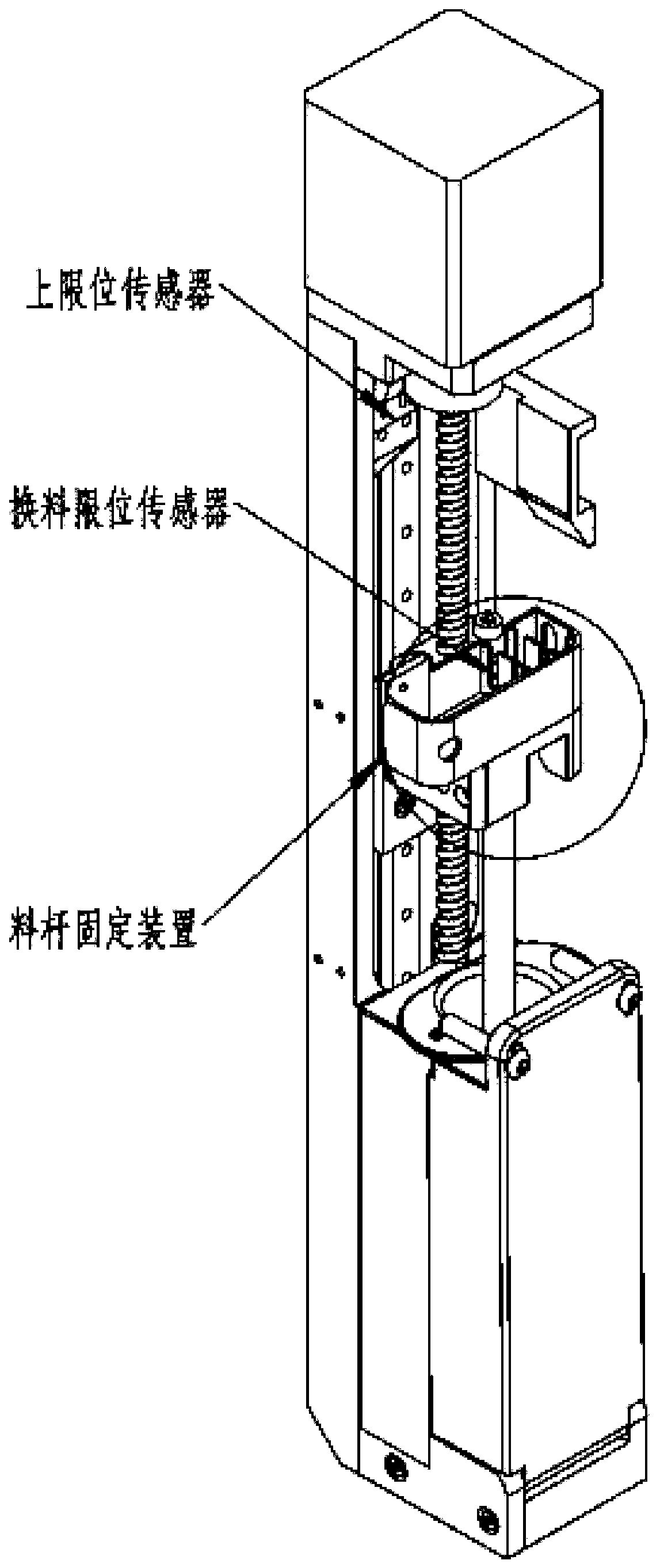
[0043] Combine below Figure 1-4 To explain this embodiment, a method for calculating the material quantity of a material tube of a material tube piston extrusion 3D printer includes the following steps:
[0044] Step 1: An upper limit sensor is arranged at the upper end of the Z-axis direction of the material rod fixing device, and a material rod limit sensor is arranged on the material rod fixing device;
[0045] Step 1: Place the material tube on the material rod fixing device, the position where the material rod fixing device touches the upper limit sensor is the zero point, and the position from the upper limit sensor to the bottom extruder is the maximum movement distance;
[0046] Step 3: Start the material rod fixing device from zero to move in the Z-axis direction, and the material tube moves until the bottom extruder touches the material rod limit sensor, and record the movement distance of the material rod fixing device;
[0047] Step 4: The maximum movement distance minus ...
specific Embodiment approach 2
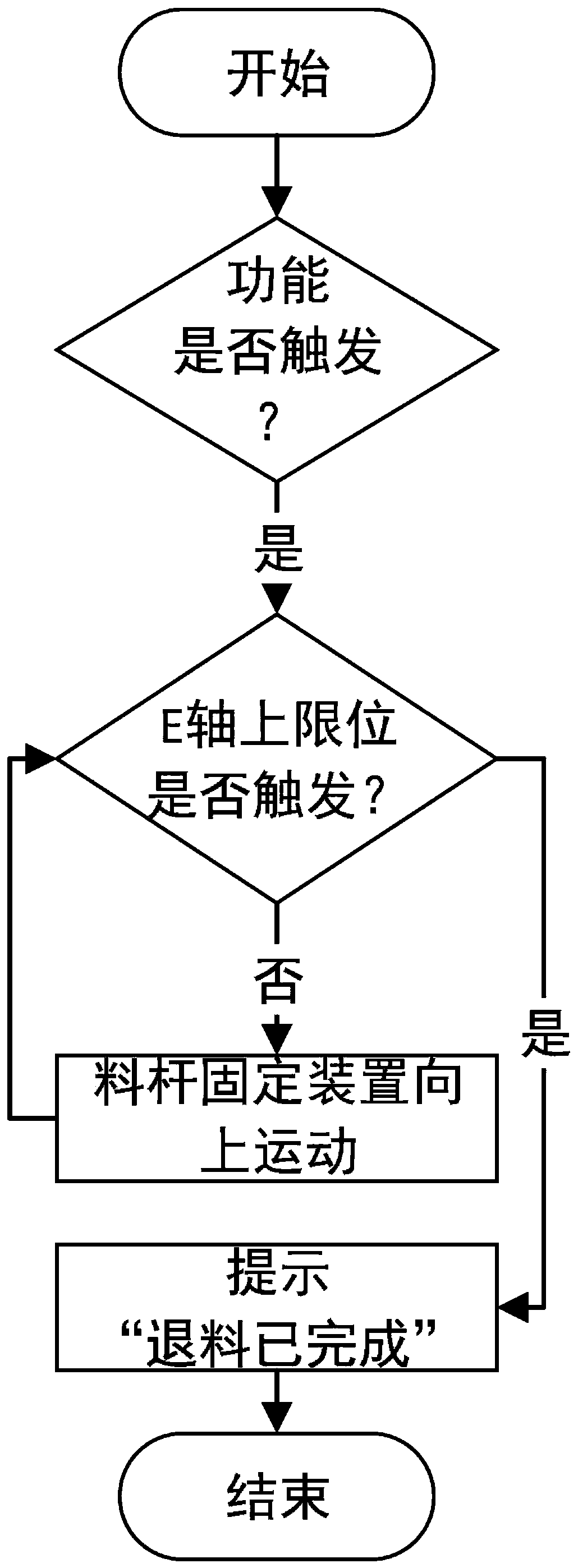
[0050] Combine below Figure 1-4 To explain this embodiment, a material return method of a material pipe material quantity calculation method of a material pipe piston extrusion 3D printer, the method includes the following steps:
[0051] Step 1: An upper limit sensor is arranged at the upper end of the Z-axis direction of the material rod fixing device, and a material rod limit sensor is arranged on the material rod fixing device;
[0052] Step 2: Trigger the 3D printer withdrawing switch, the material rod fixing device moves upwards, the material rod fixing device upwards contacts the upper limit sensor, and the position where the material rod fixing device touches the upper limit sensor is zero;
[0053] Step 3: The material rod fixing device is at the zero point and the material return is completed.
[0054] Such as figure 1 As shown, an upper limit sensor and a material rod limit sensor are provided on the barrel piston extrusion 3D printer, such as figure 2 As shown, to trigge...
specific Embodiment approach 3
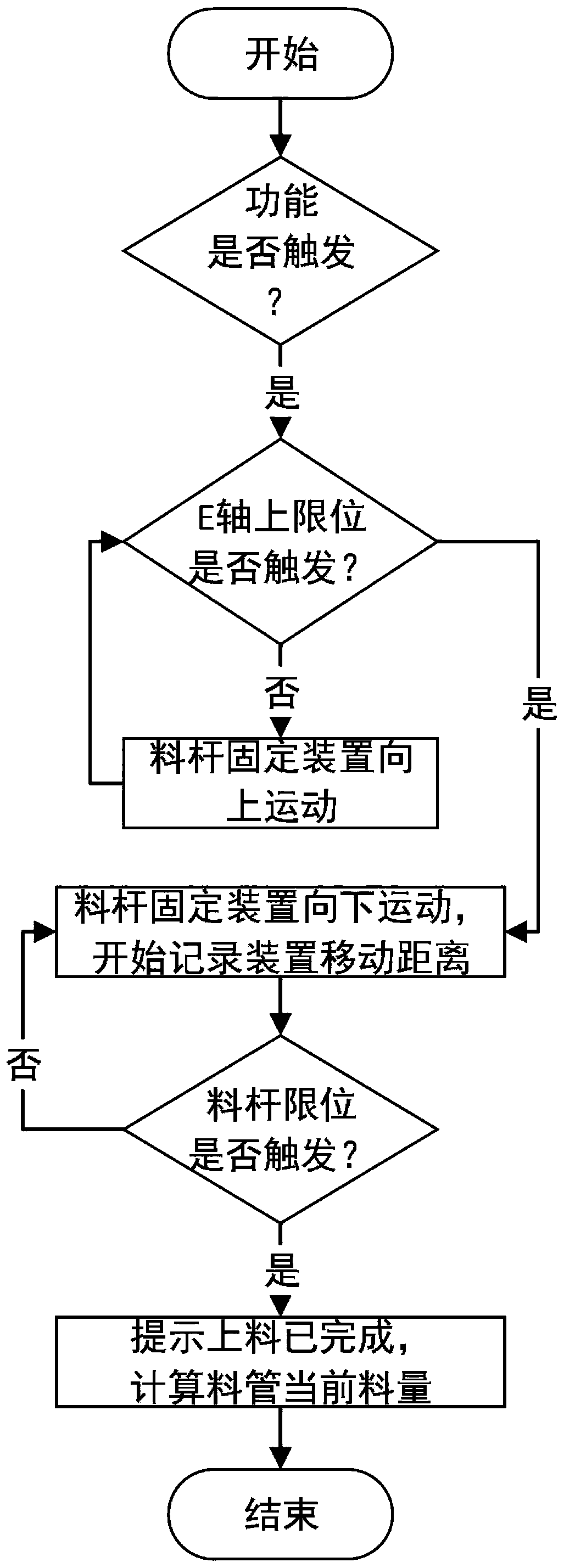
[0056] Combine below Figure 1-4 In this embodiment, a method for calculating the amount of material of a barrel of a barrel piston extrusion 3D printer is described. The method includes the following steps:
[0057] Step 1: An upper limit sensor is arranged at the upper end of the Z-axis direction of the material rod fixing device, and a material rod limit sensor is arranged on the material rod fixing device;
[0058] Step 2: Place the material tube on the material rod fixing device, trigger the 3D printer feeding switch, the material rod fixing device moves upward, the material rod fixing device upwards and the upper limit sensor is in contact, and the position where the material rod fixing device touches the upper limit sensor is Zero point, the maximum movement distance from the upper limit sensor to the position of the bottom extrusion head;
[0059] Step 3: After the material rod fixing device contacts the upper limit sensor, it moves downwards, and the material tube moves unt...
PUM
 Abstract
Description
Claims
Application Information
 - R&D Engineer
- R&D Manager
- IP Professional
- Industry Leading Data Capabilities
- Powerful AI technology
- Patent DNA Extraction
Browse by: Latest US Patents, China's latest patents, Technical Efficacy Thesaurus, Application Domain, Technology Topic, Popular Technical Reports.
© 2024 PatSnap. All rights reserved.Legal|Privacy policy|Modern Slavery Act Transparency Statement|Sitemap|About US| Contact US: help@patsnap.com


