
Installation tool for a hidden fastener and installation method for a fastener

A technology for installing tools and fasteners, applied in the direction of threaded fasteners, manufacturing tools, motor tools, etc., can solve problems such as damage to the grasping part, and achieve the effect of simple structure and mechanically stable structure

Active Publication Date: 2019-09-24
LISI AEROSPACE
View PDF6 Cites 2 Cited by
  • Summary
  • Abstract
  • Description
  • Claims
  • Application Information

AI Technical Summary

Problems solved by technology

In this last type, the grip is broken under the application of a predetermined torque

Method used


Image

  • Installation tool for a hidden fastener and installation method for a fastener
  • Installation tool for a hidden fastener and installation method for a fastener
  • Installation tool for a hidden fastener and installation method for a fastener

Examples


Embodiment Construction

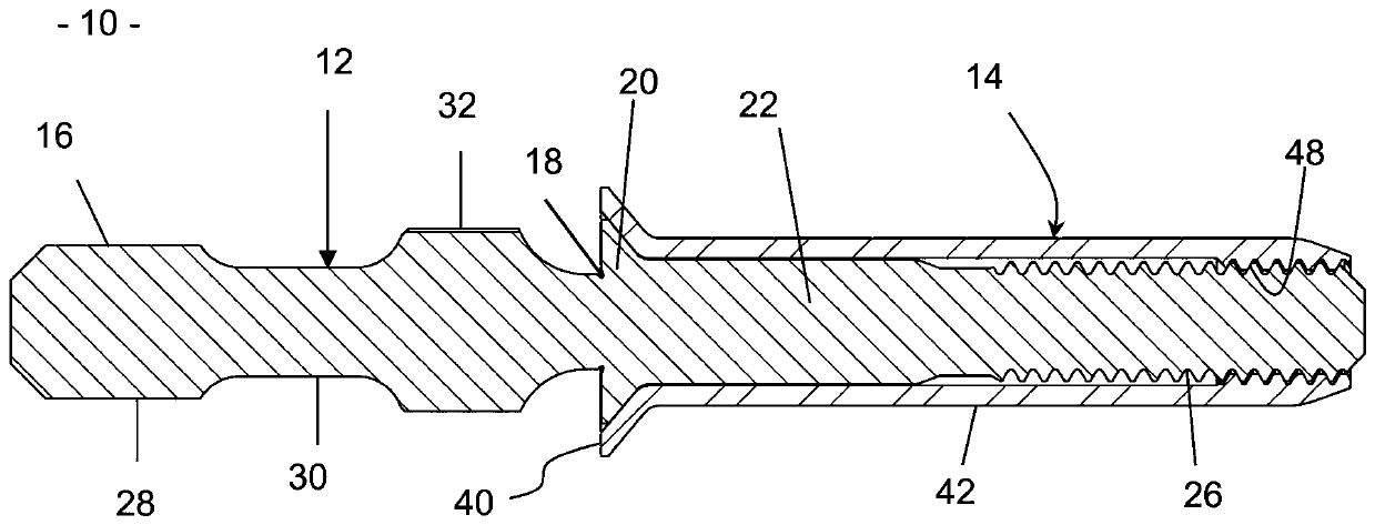
[0040] in the attached figure 1 Among them, the "pull screw" type fastener 10 applied in the present invention includes a screw 12 and a sleeve 14 . The screw 12 includes a grip 16 that can be broken during installation of the fastener, a breakout groove 18 , a milling head 20 , a post 22 and a threaded end 26 . The gripping portion 16 includes a cylindrical first gripping portion 28 , a blocking portion 30 and a second gripping portion 32 with grooves distributed on its outer surface.

[0041] The sleeve 14 includes an enlarged collar 40 for receiving the countersink 20 of the screw, and a tubular shaft 42 including a sleeve shaft 48 disposed at the end of the sleeve 14 opposite the collar 40 . The threading of the screw 12 and the threading of the threaded sleeve 14 are complementary. The tubular shaft 42 includes a deformable area (not shown in the figure), whose stiffness is lower than that of other parts, capable of forming a spherical protrusion under the action of tra...


PUM


Abstract

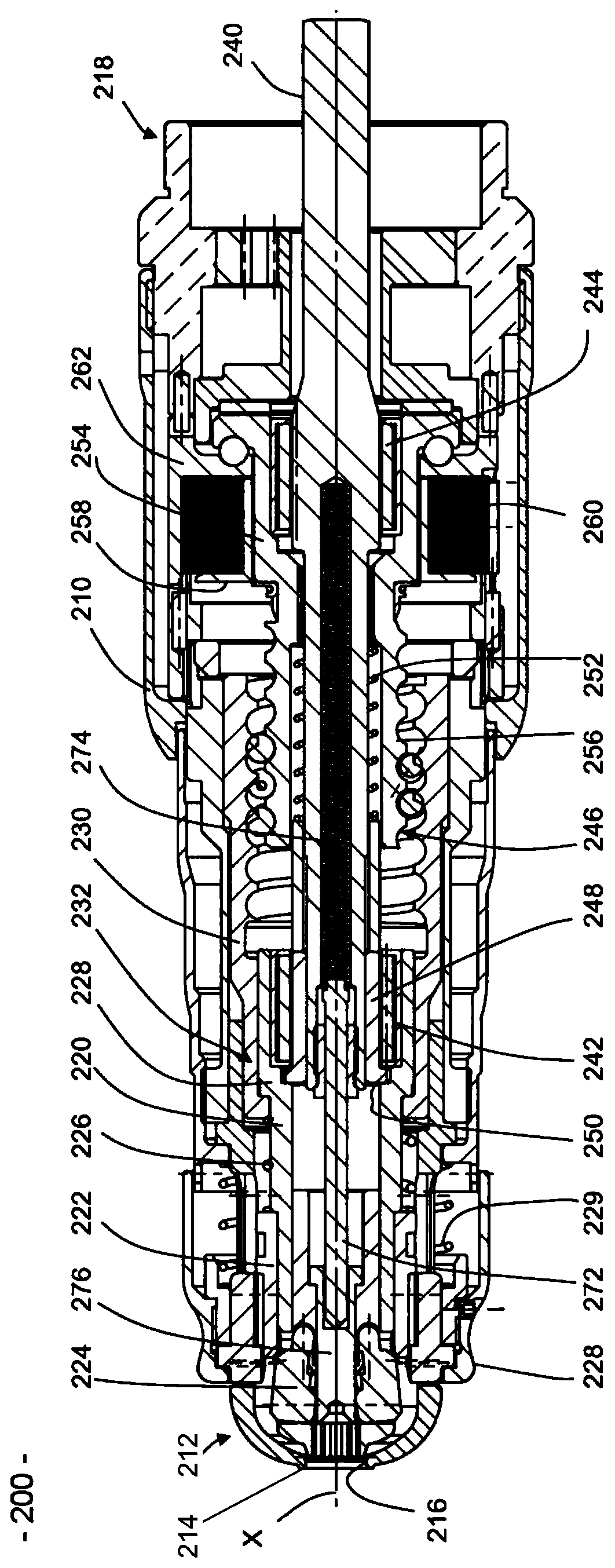
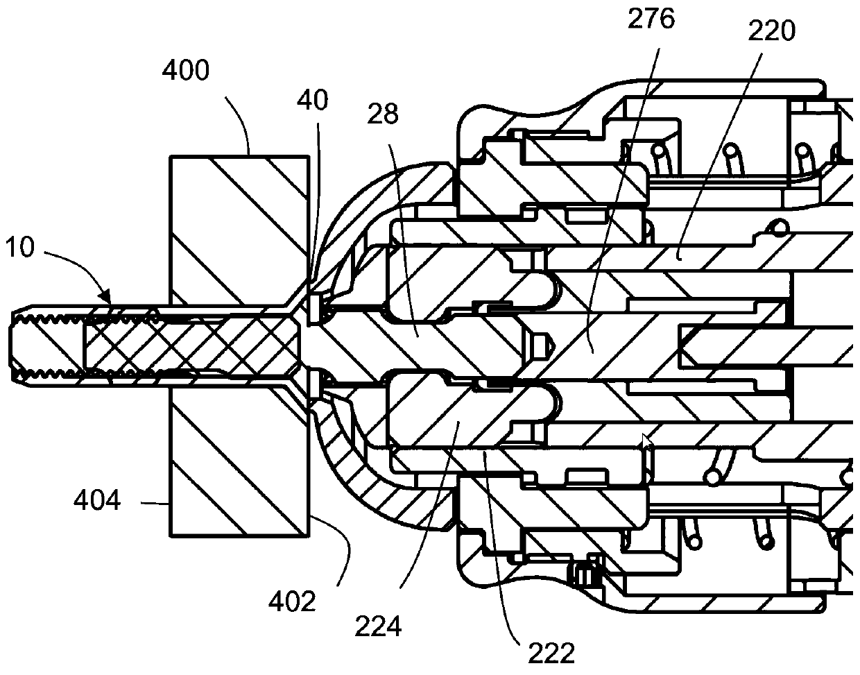
The invention relates to a tool (installation tool) for blind fasteners 10 of the ''pull-torqued'' type in a structure 400. The fastener comprises a gripping part which can be damanged. The installation tool comprises: a body, a first sleeve 220 movable axially and rotationally in the body, capable of driving the gripping element of the pin in axial translation and in rotation around the X axis, a second sleeve movable axially in the body and immovable rotationally, and a drive means comprising a rotary shaft. The shaft comprises a first free wheel for driving the first sleeve in rotation, a second free wheel, and a driving element positioned coaxially around the second free wheel. The driving element cooperates using a helical link with the second sleeve. The first free wheel drives the first sleeve in rotation in a first rotation direction of the shaft. The second free wheel brings the driving element in rotation in a second rotation direction of the shaft to move the second sleeve axially. Therefore, the installation tool can pull the fastener in a single operation step for forming a spherical projection at the blind side of a structure, tightens a screw and makes the gripping part be broken.

Description

technical field [0001] The present invention relates to a tool for installing blind fasteners in structures. Background technique [0002] What we commonly call a "blind" fastener is a fastener that can be deformed in a structure to be assembled by deforming a portion of the fastener on the rear side (accessible or not) of the structure Instead, only on one side, called the front or accessible side, is mounted the structure to be assembled. Said deformed part of the fastener is deformed radially outwards during pulling or tightening, forming a spherical or flower-shaped protrusion, said deformation bearing on the rear side. Thus, the structure to be assembled is tightly fixed, abutting between the head of the fastener on the front side and the deformed part on the rear side. [0003] Of the various types of blind fasteners, there is a first type known as a "blind rivet," which consists of a sleeve and a breakable mandrel attached to one end of the fastener by applying only...

Claims


Application Information

Patent Timeline
IPC IPC(8): B25B21/00B25F5/00
CPCB25B21/00B25F5/001F16B19/1054F16B19/1072B21J15/043B21J15/12B21J15/26B21J15/365B25B27/0007B25B23/10B25B23/0035B25B23/147B21J15/045B21J15/105Y10T29/5373B21J15/022B21J15/142B21J15/10B21J15/16
Inventor 让-吕克·莱热奥雷利恩·巴查尔布坎
Owner LISI AEROSPACE
Learn More