
Optical adjustment and control structure, backlight module and display device

An optical control and backlight module technology, applied in identification devices, instruments, etc., can solve the problem of uneven distribution of light and dark, and achieve the effects of improving display quality, enhancing light reflection, and improving uniformity

Active Publication Date: 2019-09-20
HKC CORP LTD +1
View PDF4 Cites 0 Cited by
  • Summary
  • Abstract
  • Description
  • Claims
  • Application Information

AI Technical Summary

Problems solved by technology

[0002] The optical control structure is widely used in the backlight module. The light emitted by the light source is guided by the optical control structure and the transmission direction or distribution mode of the light emitted by the light source is adjusted, and then exits the backlight module. However, although the backlight module has The optical control structure is used to adjust the transmission direction or distribution of light, but there will still be some uneven distribution of light and dark. Therefore, how to make the backlight module emit light with uniform brightness has always been the goal of this field.

Method used


Image

  • Optical adjustment and control structure, backlight module and display device
  • Optical adjustment and control structure, backlight module and display device
  • Optical adjustment and control structure, backlight module and display device

Examples


Embodiment Construction

[0046] The following will clearly and completely describe the technical solutions in the embodiments of the present invention with reference to the accompanying drawings in the embodiments of the present invention. Obviously, the described embodiments are only part of the embodiments of the present invention, not all of them. Based on the embodiments of the present invention, all other embodiments obtained by persons of ordinary skill in the art without creative efforts fall within the protection scope of the present invention.

[0047] It should be noted that if there is a directional indication (such as up, down, left, right, front, back...) in the embodiment of the present invention, the directional indication is only used to explain the position in a certain posture (as shown in the accompanying drawing). If the specific posture changes, the directional indication will also change accordingly.

[0048] In addition, if there are descriptions involving "first", "second" and ...


PUM


Abstract

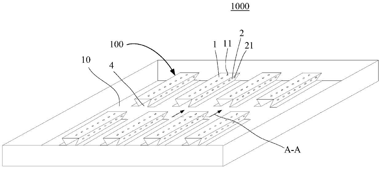
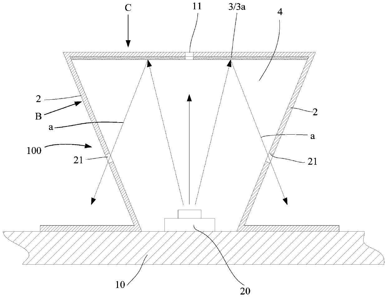
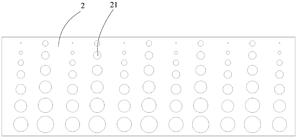
The invention discloses an optical adjustment and control structure, a backlight module and a display device. The optical adjustment and control structure includes a top plate, two side plates and a light adjusting structure, one ends of the two side plates are correspondingly connected with the top plate, the other ends of the two side plates are correspondingly used for being installed on a reflection bottom plate to form an adjustment and control space with the top plate, wherein the adjustment and control space is used for covering a light source, first light transmission holes are formed in one side plate in a penetrating mode, and the light adjusting structure is arranged on the inner side wall of the top plate and used for increasing the number of light rays, reflected from the top plate and then passing through the first light transmission holes to penetrate out of the adjustment control space, of the light source. According to the technical scheme, the light adjusting structure is arranged on the inner side wall of the top plate, the effect of enhancing light ray reflection is achieved or the transmission direction of part of the light rays is changed, the number of the light rays, reflected from the top plate and then passing through the first light transmission holes to penetrate out of the adjustment control space, of the light source is increased, the uniformity of light distribution is improved, the display quality is also improved.

Description

technical field [0001] The invention relates to the technical field of flat panel displays, in particular to an optical control structure, a backlight module and a display device. Background technique [0002] The optical control structure is widely used in the backlight module. The light emitted by the light source is guided by the optical control structure and the transmission direction or distribution mode of the light emitted by the light source is adjusted, and then exits the backlight module. However, although the backlight module has The optical control structure is used to adjust the transmission direction or distribution of light, but there is still some uneven distribution of light and dark. Therefore, how to make the backlight module emit light with uniform brightness has always been the goal of this field. Contents of the invention [0003] The main purpose of the present invention is to provide an optical control structure, a backlight module and a display dev...

Claims


Application Information

Patent Timeline
Patent Type & Authority Applications(China)
IPC IPC(8): G09F9/00
CPCG09F9/00
Inventor 康志聪王天雪顾毓波
Owner HKC CORP LTD
Learn More