Workpiece detection method, device and equipment and storage medium
A workpiece detection and workpiece technology, applied in the field of machine vision detection, can solve the problems of slow processing speed and slow interaction speed between processes, and achieve the effect of improving processing speed and accelerating interaction speed
- Summary
- Abstract
- Description
- Claims
- Application Information
AI Technical Summary
Problems solved by technology
Method used
Image

Examples
Embodiment 1
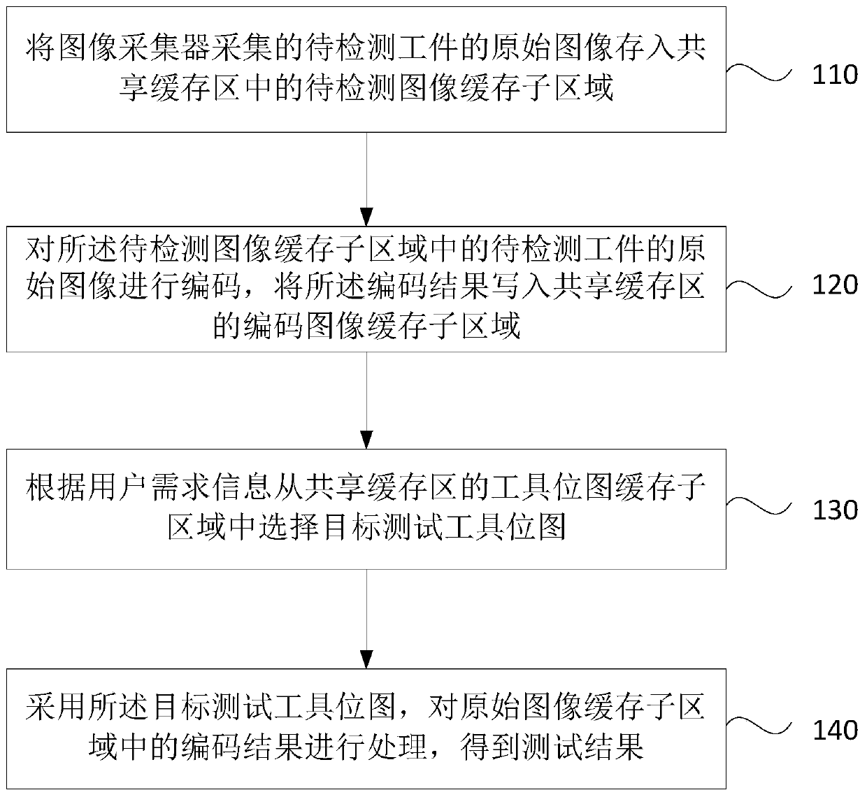
[0045] figure 1 It is a flow chart of a workpiece detection method provided by Embodiment 1 of the present invention. The technical solution provided by this embodiment is applicable to the situation where a workpiece needs to be detected. The method can be executed by a workpiece detection device, which can be implemented by hardware and / or Or software implementation, the method specifically includes:
[0046] Step 110, storing the original image of the workpiece to be inspected collected by the image collector into the image buffer sub-area to be inspected in the shared buffer area.
[0047] Among them, the image collector is a device responsible for collecting the image of the workpiece; the workpiece to be inspected is the workpiece that needs to be inspected; the original image refers to the unprocessed original result of the workpiece to be inspected obtained through the image collector. The shared cache area is a pre-divided area in the memory provided by the system, w...
Embodiment 2
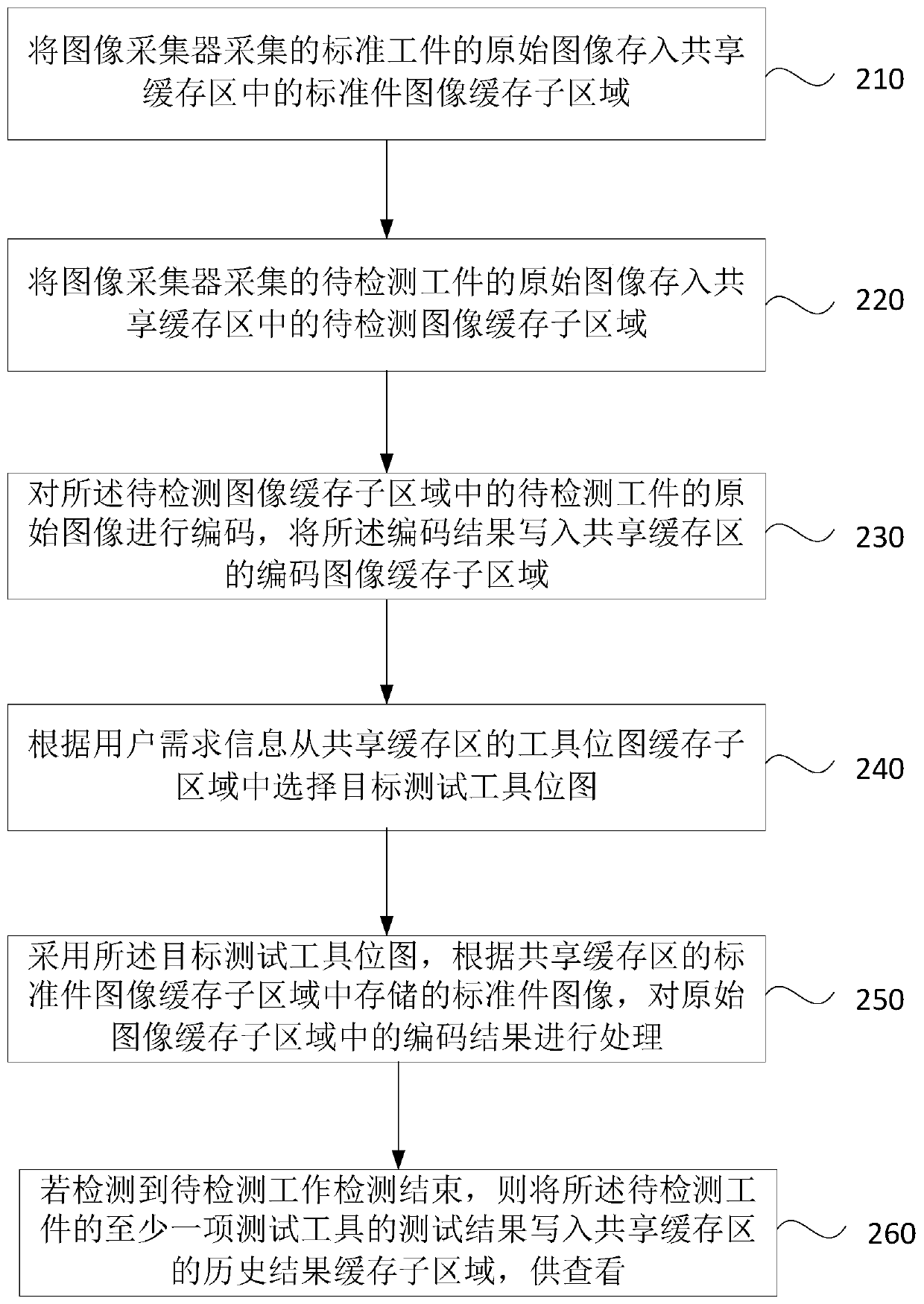
[0063] figure 2 It is a flow chart of a workpiece detection method provided by Embodiment 2 of the present invention. This embodiment is further refined on the basis of the above-mentioned technical solution. For details not described in detail in this embodiment, refer to Embodiment 1. Such as figure 2 As shown, the method specifically includes:
[0064] Step 210, storing the original image of the standard workpiece captured by the image collector into the standard part image cache sub-area in the shared buffer area.
[0065] Among them, the standard workpiece refers to the template workpiece of the workpiece to be detected, which is the reference workpiece of the workpiece detection tool to be detected; the standard part image cache sub-area is the cache in the shared buffer area that is pre-set to store the original image of the standard part acquired by the image collector Area. The original image of the standard workpiece of the workpiece to be detected is obtained i...
Embodiment 3
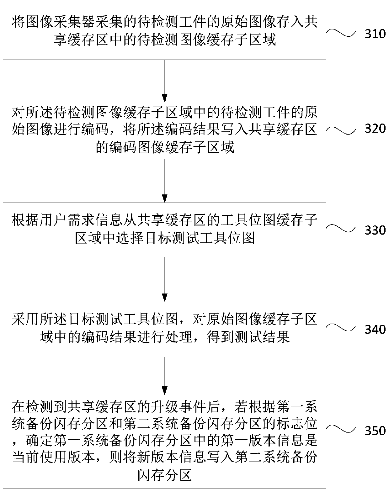
[0087] image 3 It is a flow chart of a workpiece detection method provided by Embodiment 3 of the present invention. This embodiment is further refined on the basis of the above-mentioned technical solution. For details that are not described in detail in this embodiment, please refer to the above-mentioned embodiment. Such as image 3 As shown, the method specifically includes:
[0088] Step 310, storing the original image of the workpiece to be inspected collected by the image collector into the image buffer sub-area to be inspected in the shared buffer area.
[0089]Step 320: Encode the original image of the workpiece to be inspected in the image to be inspected buffer sub-area, and write the encoding result into the encoded image buffer sub-area of the shared buffer area.
[0090] Step 330 , selecting the target test tool bitmap from the tool bitmap cache sub-area of the shared buffer area according to the user requirement information.
[0091] Step 340: Using the ...
PUM
 Abstract
Description
Claims
Application Information
 - R&D
- Intellectual Property
- Life Sciences
- Materials
- Tech Scout
- Unparalleled Data Quality
- Higher Quality Content
- 60% Fewer Hallucinations
Browse by: Latest US Patents, China's latest patents, Technical Efficacy Thesaurus, Application Domain, Technology Topic, Popular Technical Reports.
© 2025 PatSnap. All rights reserved.Legal|Privacy policy|Modern Slavery Act Transparency Statement|Sitemap|About US| Contact US: help@patsnap.com